Smelting method of high cleanliness steel

A technology with high cleanliness and smelting method, which is applied in the field of iron and steel smelting, can solve the problems of high-end steel relying on imports and difficulties in the cleanliness of molten steel, and achieve the effects of low alloy cost, low cost, and prevention of contamination

Active Publication Date: 2022-03-22
PANZHIHUA IRON & STEEL RES INST OF PANGANG GROUP
View PDF0 Cites 0 Cited by
  • Summary
  • Abstract
  • Description
  • Claims
  • Application Information

AI Technical Summary

Problems solved by technology

Therefore, it is very difficult to further improve the cleanliness of molten steel.
However, there is still a certain gap between my country's molten steel cleanliness control level and the world's advanced level, resulting in the current high-end steel products in my country mainly relying on imports

Method used


Image

  • Smelting method of high cleanliness steel
  • Smelting method of high cleanliness steel

Examples


Embodiment 1

[0037] Embodiment 1 adopts the method of the present invention to smelt high-cleanliness steel

[0038] The specific operation steps are as follows:

[0039] When tapping 1 / 4 of the converter, add aluminum-iron and silicon-manganese to the ladle to deoxidize the molten steel. After deoxidation, the oxygen is controlled at 0.02%. After tapping, the molten steel is stirred by weak argon blowing. The argon blowing time is 10 minutes to ensure that the deoxidized inclusions fully float up.

[0040] After the molten steel reaches the LF process, the aluminum wire is fed into the molten steel to deoxidize the molten steel so that the oxygen activity in the steel is 10×10 -4 %, heat the molten steel for 5 minutes to dissolve slag, add ferrosilicon to alloy the molten steel, blow argon and stir for 3 minutes, and then add ferromanganese to alloy the molten steel.

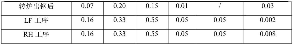
[0041] The components after converter tapping and LF process alloying are shown in Table 2:

[0042] Table 2 Steel com...

Embodiment 2

[0046] Embodiment 2 adopts the method of the present invention to smelt high-cleanliness steel

[0047] The specific operation steps are as follows:

[0048] When tapping 1 / 3 of the converter, add silicon calcium barium to the ladle to deoxidize the molten steel. After deoxidation, the oxygen is controlled at 0.03%. The time is 4 minutes to ensure that the inclusions after deoxidation fully float up.

[0049] After the molten steel reaches the LF process, add aluminum pellets to the molten steel and heat the molten steel to slag and deoxidize alloying for 5 minutes, and then measure the oxygen activity of the molten steel to 20×10 -4 %, then add silico-manganese to alloy the molten steel, blow argon and stir for 5 minutes, and then add metal manganese to alloy the molten steel.

[0050] The components after converter tapping and LF process alloying are shown in Table 3:

[0051] Table 3 Steel composition / %

[0052]

[0053]

[0054] When the molten steel reaches the ...


PUM

PropertyMeasurementUnit
thicknessaaaaaaaaaa

Abstract

The invention belongs to the technical field of iron and steel smelting, and in particular relates to a method for smelting high-cleanliness steel. In order to further improve the cleanliness of molten steel in the smelting process and improve the quality of steel, the present invention provides a method for smelting high-cleanliness steel, which includes the following steps: the molten steel is smelted using the "converter-LF-RH-continuous casting" process, and the molten steel is in the converter The tapping process, LF process and RH process are carried out step by step for deoxidation and alloying; when the molten steel reaches the RH treatment station, a slag blocking device is installed at the RH insertion nozzle, and then immersed in the molten steel, the insertion depth is 500-650mm; vacuum treatment 18 ~25min, after vacuum treatment, blow argon and stir weakly for 3~8min, prevent the molten steel from being exposed during the argon blowing process. The invention specially designs a RH insertion tube slag blocking device, which effectively isolates the ladle slag from entering the insertion tube during the insertion tube's immersion into the molten steel, preventing the molten steel from being polluted, combined with step-by-step deoxidation, to jointly make the molten steel clean The degree has been significantly improved and has a good application prospect.

Description

technical field [0001] The invention belongs to the technical field of iron and steel smelting, and in particular relates to a method for smelting high-cleanliness steel. Background technique [0002] With the maturity of the clean steel smelting process in the modern iron and steel industry, the cleanliness control of molten steel has reached a relatively stable level, and it is difficult to make great progress. To break through this bottleneck, it is difficult to make a relatively large improvement from the study of thermodynamics and kinetics alone. [0003] At present, in the production of clean steel, most manufacturers will adopt a vacuum treatment process, the purpose of which is to degas and remove inclusions in the steel through vacuum circulation. However, when the insertion pipe is immersed in the molten steel, the ladle slag on the molten steel surface is inevitably brought into the molten steel together, and mixed with the molten steel during the circulation pr...

Claims


Application Information

Patent Timeline
Patent Type & Authority Patents(China)
IPC IPC(8): C21C7/10C21C7/06C21C7/00C22C38/02C22C38/04C22C38/06C22C38/14
CPCC21C7/10C21C7/06C21C7/0006C21C7/0087C22C38/02C22C38/04C22C38/06C22C38/14Y02P10/20
Inventor 张敏彭宏亮雷辉李锡福
Owner PANZHIHUA IRON & STEEL RES INST OF PANGANG GROUP
Why Eureka
Try Eureka