Free-form surface spectrometer optical system and design method

An optical system and spectrometer technology, applied in spectrometry/spectrophotometry/monochromator, optical radiometry, using diffractive elements to generate spectra, etc. Unfavorable processing, weak F-number and field of view adaptability, etc., achieve the effect of strong aberration correction ability, strong distortion correction ability, and widening layout space

Inactive Publication Date: 2020-08-21
SHANGHAI INST OF TECHNICAL PHYSICS - CHINESE ACAD OF SCI
View PDF3 Cites 0 Cited by
  • Summary
  • Abstract
  • Description
  • Claims
  • Application Information

AI Technical Summary

Problems solved by technology

[0003] The main problems in the existing technology are: compared with the planar grating, the curved grating is more difficult and costly to develop; the F number and field of view adaptability of the existing free-form surface spectrometer optical system are weaker, and the residual aberration and distortion are larger. The large difference in sagittal height between the free-form surface and the nearest rotational surface is not conducive to processing, or a certain inclination between optical elements is not conducive to structural design and adjustment; The space at the place is often inconvenient for the layout of the detector, and the optical path needs to be turned

Method used


Image

  • Free-form surface spectrometer optical system and design method
  • Free-form surface spectrometer optical system and design method
  • Free-form surface spectrometer optical system and design method

Examples


Embodiment Construction

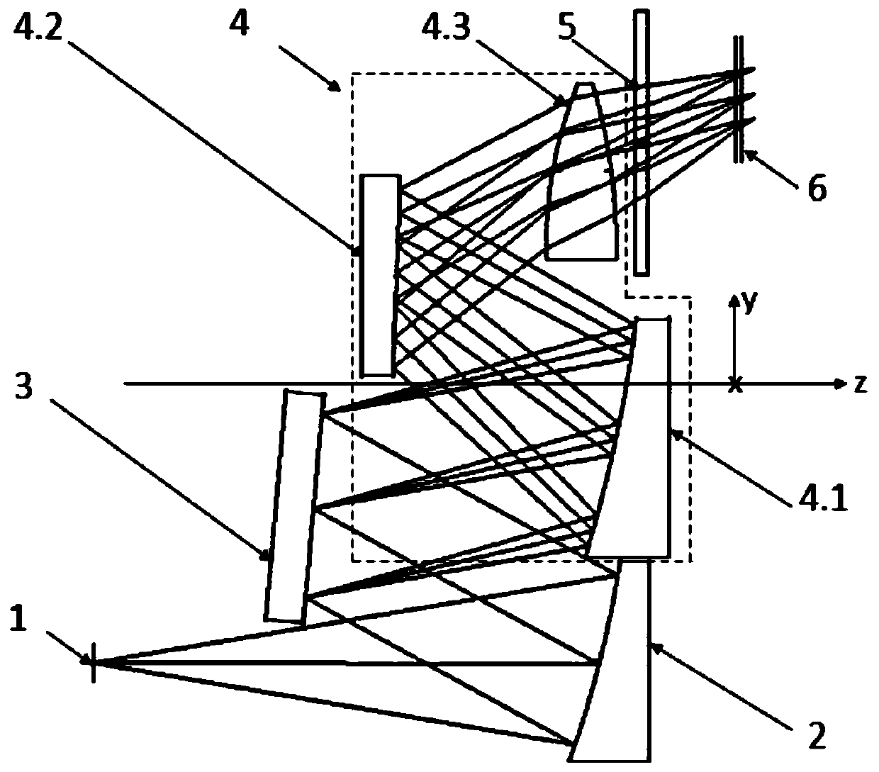
[0014] The following is based on figure 1 , give a better embodiment of the present invention and elaborate:

[0015] To design a short-medium wave infrared free-form surface spectrometer, the size of the detector array used is 512 elements × 320 elements, and the pixel size is 25 μm × 25 μm. The design index requirements are listed in Table 1.

[0016] Table 1

[0017] Spectral range F number Horizontal magnification Slit length Dispersion width 1.0-3.4μm 3.0 -1× 12.8mm 8.0mm

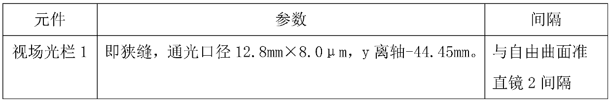
[0018] Design data are listed in Table 2.

[0019] Table 2

[0020]

[0021]

[0022]

[0023] The design result is: the object space telecentricity of the spectrometer. The spectrometer normalizes 0 field of view, 0.707 field of view and 1 field of view, and the rms diameter of the spot diagram representing wavelengths of 1.0 μm, 2.2 μm and 3.4 μm is less than 5.6 μm, and the pixel size is less than 25 μm. At the Nyquist cut-off frequency of 20pl / mm, the ...


PUM


Abstract

The invention discloses a free-form surface spectrometer optical system and a design method. The free-form surface spectrometer optical system is composed of a field diaphragm, a free-form surface collimating mirror, a plane grating, a convergent mirror, a detector window and an optical filter. Specifically, the convergent mirror comprises two free-form surface reflecting mirrors and a correctionlens. Light from the object side starts from the field diaphragm, reaches the grating after being reflected by the collimating mirror, is diffracted by the grating, then is reflected by a first free-form surface mirror of the convergent mirror, is reflected by a second free-form surface mirror, is refracted by the correction lens, then reaches a Dewar window and the optical filter, and finally reaches the image surface. The combination of the free-form surface reflecting mirrors and the correction lens is beneficial to further correction of spectral distortion and image quality. The inventionhas the advantages that: the optical path layout is convenient, the distortion is low, the aberration correction capability is strong, the image surface inclination is small, the design requirements of a long slit and a small F number can also be met, optical axes of optical elements with focal power are parallel, and the optical elements with focal power are easy to assemble and adjust.

Description

technical field [0001] The invention relates to an optical system and optical design, in particular to an optical system of a free-form surface spectrometer and a design method thereof. Background technique [0002] For spectrometers used in imaging spectrometers, the design of the optical system needs to take into account the control of image quality, pupil position and distortion. The spectrometer optical system that uses curved gratings to split light is better in terms of image quality and distortion control, but curved gratings have relatively high requirements for ultra-precision manufacturing, and the production cost is relatively high. Thanks to the development of modern ultra-precision machining technology, the processing and manufacturing of high-precision free-form surfaces has become easy to realize. Therefore, planar grating spectrometers based on complex surfaces such as free-form surfaces are also optional high-performance solutions. [0003] The main problem...

Claims


Application Information

Patent Timeline
IPC IPC(8): G01J3/28G01J3/02G01J3/18
CPCG01J3/2823G01J3/0208G01J3/1804G01J2003/2866
Inventor 袁立银谢佳楠何志平
Owner SHANGHAI INST OF TECHNICAL PHYSICS - CHINESE ACAD OF SCI
Why Eureka
Try Eureka