Rotary stack riveted motor rotor core

A rotor core and motor rotor technology, which is applied in the manufacture of squirrel cage rotors, stator/rotor bodies, magnetic circuit rotating parts, etc., can solve the problem that the jump cannot be eliminated, the magnetic circuit of the rotor core is uneven, and the quality of the core is reduced and other problems, to achieve the effect of saving mechanical finishing process, good flatness and consistency, and improving service life

Active Publication Date: 2019-02-22
浙江迪贝电气股份有限公司
View PDF4 Cites 0 Cited by
  • Summary
  • Abstract
  • Description
  • Claims
  • Application Information

AI Technical Summary

Problems solved by technology

[0007] 1. There is a thickness difference in the stamping material of cold-stamped silicon steel sheet. The cumulative error generated during the lamination process of the rotor punching sheet leads to a certain height deviation at both ends of the formed rotor core. Due to the rotation angle of the rotor punching sheet after punching and riveting Extremely small, unable to fully and effectively eliminate the height deviation at both ends of the rotor core, resulting in unevenness at both ends of the rotor core;
[0008] 2. Due to the insurmountable precision problems of the stamping die, there are precision errors in the inner and outer circle dimensions and groove dimensions of the rotor punching sheet, resulting in a certain shape and position deviation of the stacked riveted rotor core, resulting in a warp dimension deviation of the rotor Large, the radial imbalance is too large, resulting in uneven magnetic circuit of the rotor core;
[0009] 3. Since the cold-rolled silicon steel sheet is formed by rolling, the rolling direction and transverse magnetic properties (magnetic conduction) are inconsistent, which also makes the magnetic circuit of the rotor core uneven
[0010] To sum up, ①When the rotor rotates at high speed, it will inevitably lead to large noise and vibration of the motor, which will reduce the service life of the motor; ②Because the beating caused by the inner and outer circles of the rotor core cannot be eliminated, it is necessary to add mechanical finishing processes , that is, grinding the inner and outer circles. This supplementary processing not only wastes man-hours but also reduces the quality of the iron core and deteriorates the performance of the motor.

Method used


Image

  • Rotary stack riveted motor rotor core
  • Rotary stack riveted motor rotor core
  • Rotary stack riveted motor rotor core

Examples


Embodiment 1

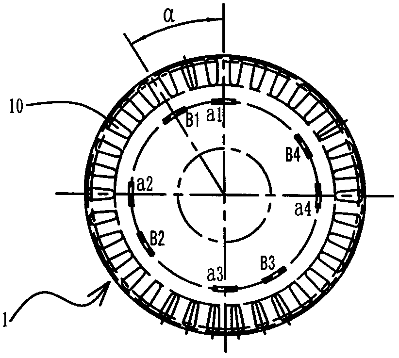
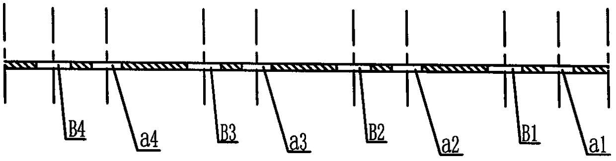
[0054] The illustration of the present embodiment, the adopted material thickness is roughly the bar of d=0.5mm, and the number n=100 of the annular rotor stamping sheets (the number n of the rotor stamping sheets 1 whose sheet thickness is definite is determined by the rotor iron core Depending on the stacking height requirements, the stacking height of the rotor core is H=50mm), the slots of the rotor core to be manufactured and the slots of the stator core are matched as follows: The number of slots Z=24.

[0055] Please refer to Picture 1-1, 1-2 , 1-3, 2-1, 2-2, 2-3, 2-4, 3-1, 3-2, 3-3, 3-4, 4-1, 4-2, 4-3, 4 -4,

[0056] A rotary stack riveting motor rotor core, which is formed by stacking and riveting n circular rotor punches 1 with guide bar grooves evenly distributed at intervals. The number of embedding grooves Z matches.

[0057] Each rotor punch 1 has an inner circle, the above-mentioned number of guide grooves 10, an outer circle, four rivets (a1, a2, a3, a4) a...

Embodiment 2

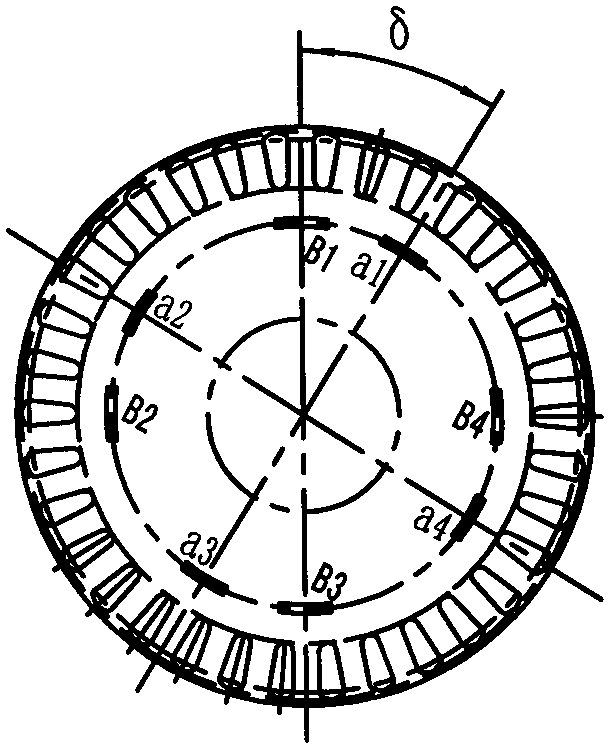
[0080] The illustration of the present embodiment, the adopted material thickness is roughly the bar of d=0.5mm, and the number n=100 of the annular rotor stamping sheets (the number n of the rotor stamping sheets 1 whose sheet thickness is definite is determined by the rotor iron core The stacking height is determined by the stacking height of the rotor core (H = 50mm). The slots of the rotor core and stator core to be manufactured are matched as follows: the number of guide bar slots for the rotor core is Q = 34, and the embedded wires of the stator core The number of slots Z=24.

[0081] Please refer to Figure 5-1 , 5-2 , 5-3, 6-1, 6-2, 6-3, 6-4, 7-1, 7-2, 7-3, 7-4, 8-1, 8-2, 8-3, 8 -4,

[0082] A rotary stack riveting motor rotor core, which is formed by stacking and riveting n circular rotor punches 1 with guide bar grooves evenly distributed at intervals. The number of embedding grooves Z matches.

[0083] Each rotor punch 1 has an inner circle, the above-mentioned...


PUM


Abstract

The invention discloses a rotary laminated and riveted motor rotor core. The rotary laminated and riveted motor rotor core is formed by laminating and riveting n rotor punching plates which are evenly distributed at intervals and are provided with conducting bar slots, wherein the number Q of the conducting bar slots of the rotor core is matched with the number Z of wire embedding grooves of a stator core; adjacent riveting sheet and through hole are taken as a group; at least three groups of riveting sheets and through holes are evenly distributed on each rotor punching plate along the circumferential direction; the included angle alpha between each group of riveting sheet and through hole is equal to 360 degrees / Q*q; q is the number of the conducting bar slots within the included angle alpha; in any two adjacent layers of rotor punching plates, the riveting sheets of the upper layer of rotor punching plates are completely riveted and connected to the inside of the through holes corresponding to the lower layer of rotor punching plates which clockwise rotate a delta-degree angle; and when the rotation angle delta of each rotor punching sheet is alpha+360 degrees / Z / n, alpha-360 degrees / Z / n and alpha, the rotor core is a clockwise chute rotor core, an anticlockwise chute rotor core and a straight chute rotor core respectively. According to the rotor core disclosed by the invention, the end surface is flat; the inner and outer circle precision and the slot precision are high; the shape position error is small; fine machining can be omitted; and a rotor is low in vibration and free of noise.

Description

【Technical field】 [0001] The invention relates to a rotary stacked riveted motor rotor rotor core, which belongs to the technical field of motor rotor manufacturing. 【Background technique】 [0002] In induction (single-phase asynchronous) motors, in order to weaken the additional torque and noise caused by the tooth harmonic magnetic field, the general cage rotor often uses inclined guide bar slots, that is, the guide bar slots are skewed by one degree relative to the stator along the shaft. angle. [0003] Now take the rotor core with four alternately evenly spaced through holes and rivets as an example to illustrate: [0004] The rotor core is formed by stacking 100 rotor punches. The rotor core and the stator core slots are matched as follows: the rotor core has 34 guide bar slots, and the stator core has 24 embedding slots. [0005] According to the requirements of the manufacturing process, the angle of the skewed rotor core after riveting is 15 degrees (equivalent to...

Claims


Application Information

Patent Timeline
Patent Type & Authority Patents(China)
IPC IPC(8): H02K1/22H02K1/26H02K15/02
CPCH02K1/22H02K1/26H02K15/0012
Inventor 邢懿烨王建鸿张小江马树江
Owner 浙江迪贝电气股份有限公司
Why Eureka
Try Eureka