Broadband Semi-elliptical Slot Antenna Array and Design Method in Millimeter Wave Antenna Level Package

A millimeter-wave antenna and slot antenna technology, applied in antenna arrays, antennas, slot antennas, etc., can solve problems such as the inability to meet the requirements of bidirectional slot antenna arrays in antenna-level packaging systems, reduce array bandwidth and gain, and fail to achieve array effects, etc. , to achieve the effect of broadband transmission, large array bandwidth and gain, and the effect of integration

Active Publication Date: 2022-03-25
ANHUI UNIVERSITY
View PDF7 Cites 0 Cited by
  • Summary
  • Abstract
  • Description
  • Claims
  • Application Information

AI Technical Summary

Problems solved by technology

[0005] In the prior art, Horng-Dean Chen proposed a square slot antenna structure with wide impedance branches, which increased the relative bandwidth of the antenna to more than 60%. F.Muge designed a 1×4 antenna array based on his research. However, the coupling between unit slots reduces the array bandwidth and gain; scholars such as Evangelos S. have proposed wide-band slot antennas with circular and elliptical slot structures and wide impedance branches, but their large size hinders high-performance and miniaturized array design; Traditional slot antennas cannot achieve a good array effect alone. Some miniaturized slot antenna arrays have low gain due to mutual coupling between array elements. Some slot antenna arrays with better gain have a narrow operating bandwidth and cannot adapt to Broadband requirements cannot meet the requirements of bi-directional slot antenna arrays in antenna-level packaging systems with wideband and high gain for narrow, long, and straight scenarios

Method used


Image

  • Broadband Semi-elliptical Slot Antenna Array and Design Method in Millimeter Wave Antenna Level Package
  • Broadband Semi-elliptical Slot Antenna Array and Design Method in Millimeter Wave Antenna Level Package
  • Broadband Semi-elliptical Slot Antenna Array and Design Method in Millimeter Wave Antenna Level Package

Examples


Embodiment 1

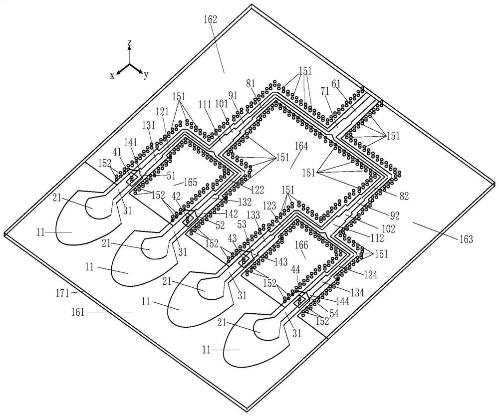
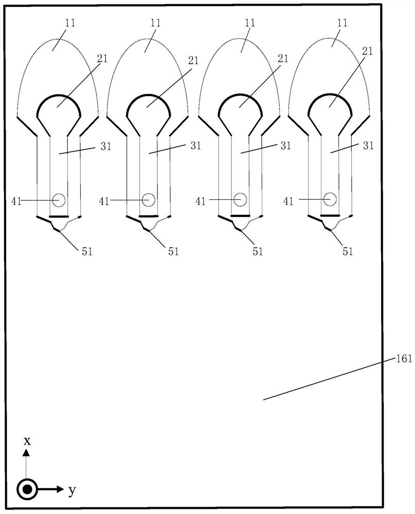
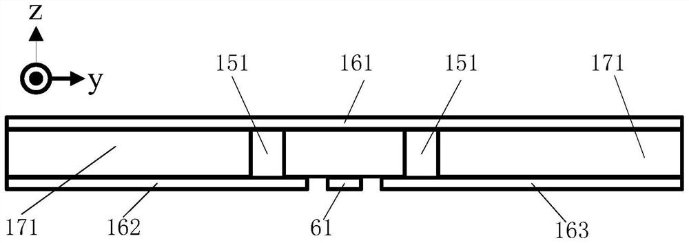
[0052] like Figure 1 to Figure 5 As shown, the broadband semi-elliptical slot antenna array in the millimeter-wave antenna-level package includes a microwave dielectric substrate 171, the microwave dielectric substrate 171 is insulated, the upper surface of the microwave dielectric substrate 171 is all covered with copper layers, and a part of the lower surface of the microwave dielectric substrate 171 is covered with copper The other part is the exposed insulating microwave dielectric substrate 171 .

[0053] Four uniformly symmetrically arranged rectangular CPW feeders 31 and four open sector branches 21 are integrally etched on the upper surface of the microwave dielectric substrate 171 from the bottom to the top along the x-axis direction; the open sector branches 21 include gradients Trapezoidal CPW transmission belt and fan-shaped transmission belt, the shape of the gradient trapezoidal CPW transmission belt is an isosceles trapezoid, and the length of the chord corresp...


PUM


Abstract

Broadband coplanar waveguide semi-elliptical slot antenna array structure in millimeter-wave antenna-level packaging, related to the field of antenna array technology, how to design an antenna array with large array bandwidth, high gain, and easy integration suitable for narrow, long and straight scenarios; including antennas An array radiation component, an antenna array feed component, and a transition structure from GCPW to CPW; the antenna array feed component excites the corresponding antenna unit through the GCPW to CPW transition structure and a rectangular CPW feeder; the antenna unit includes a first metal connection on the upper surface of the microwave dielectric substrate The etched semi-elliptical gap of the floor and the open fan-shaped branch, the semi-elliptical gap is the gap etched between the fan-shaped outer edge of the fan-shaped branch and the first metal grounding plate, and the midpoint of the chord corresponding to the fan-shaped arc of the open-circuit fan-shaped branch to the surrounding second The distance of a metal grounding plate changes gradually according to a semi-elliptical shape. Compared with the traditional circular and elliptical slot structures, the slot width is shortened, the array radiation effect is improved, and the array bandwidth and gain are larger.

Description

technical field [0001] The invention belongs to the technical field of antenna arrays in millimeter-wave communication and detection antenna-level packaging systems, and in particular relates to a broadband semi-elliptical slot antenna array in millimeter-wave antenna-level packaging and a design method. Background technique [0002] At present, with the rapid development of global communication services, wireless mobile communication technology, which is the main means of personal communication in the future, has attracted great attention. Its excellent performance plays an important role in the success or failure of wireless communication projects. At present, in the field of antennas, new antennas such as millimeter-wave broadband antennas have attracted much attention due to their advantages of high transmission rate, large system capacity, strong spatial resolution and target recognition capabilities, and small size for integration. [0003] With the increasing demand ...

Claims


Application Information

Patent Timeline
Patent Type & Authority Patents(China)
IPC IPC(8): H01Q1/36H01Q1/38H01Q1/50H01Q13/10H01Q21/00
CPCH01Q1/36H01Q1/38H01Q1/50H01Q13/106H01Q21/00
Inventor 朱浩然李坤孙玉发黄志祥吴先良
Owner ANHUI UNIVERSITY
Why Eureka
Try Eureka