
Microwave oven

A microwave oven and wavelength technology, applied in the field of microwave ovens, can solve the problems of long waveguides and difficulty in accommodating electronic components, etc.

Inactive Publication Date: 2006-03-08
SAMSUNG ELECTRONICS CO LTD
View PDF2 Cites 0 Cited by
  • Summary
  • Abstract
  • Description
  • Claims
  • Application Information

AI Technical Summary

Problems solved by technology

[0030] However, there is a problem in the conventional two-way microwave oven thus constructed that the output waveguide is long and thick, making it difficult to accommodate electronic components, and the impedance of the waveguide 19 is often changed according to the cavity 17, so once the size of the cavity 17 changes , the size and position of the upper and lower radiation holes 21a and 21b are adjusted and redesigned
[0031] In addition, there is another problem that the microwaves in the cavity 17 radiate into the cavity in different phases, and the electric field distribution pattern in the cavity 17 is not integrally formed through the upper and lower radiation holes 21a and 21b, but mainly in the upper and lower parts. form

Method used


Image

  • Microwave oven
  • Microwave oven
  • Microwave oven

Examples


Embodiment Construction

[0057] Now, will refer to Figures 7 to 1 1 The first embodiment of the present invention will be described in detail.

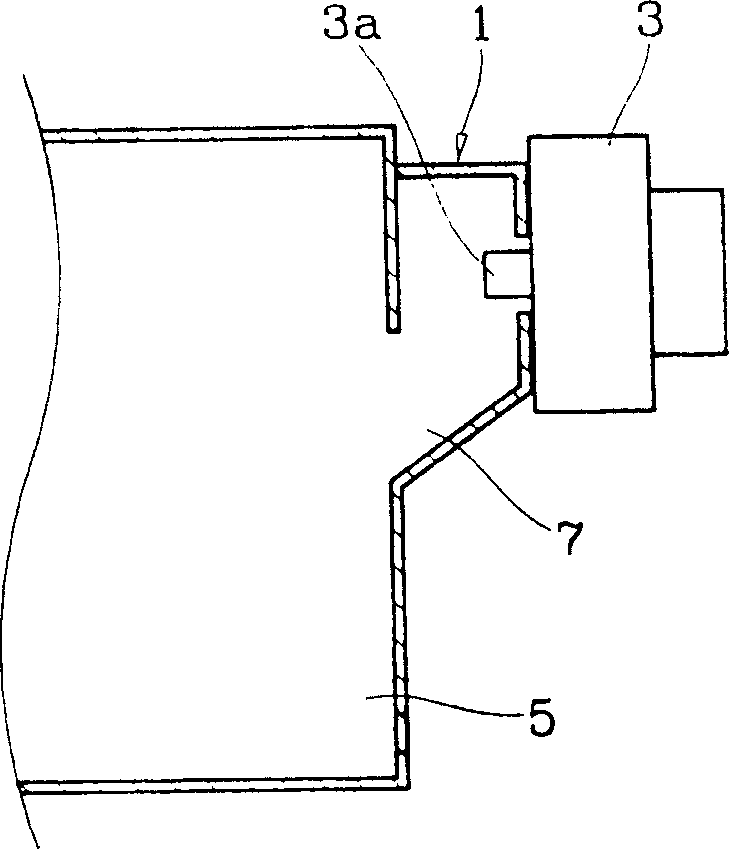
[0058] Such as Figure 7 with 8 As shown, the microwave oven of the present invention includes: a cavity 50 for accommodating cooking food; a magnetron 60 for generating microwaves with a frequency λg; and a waveguide 70 for passing the microwaves generated from the magnetron 60 through the antenna 61 into cavity 50 .

[0059] At this time, the waveguide 70 includes an input waveguide 71 and an output waveguide 72 , wherein the input waveguide 71 is connected to the magnetron 60 and transmits the microwave generated by the magnetron 60 into the output waveguide 72 .

[0060] In other words, if Figure 9 As shown, the input waveguide 71 is located at the slightly upward rear area of ​​the output waveguide 72 , and is welded to the output waveguide 72 at a predetermined angle in a trumpet shape, so as to be fixed with the output waveguide 72 .

[0061] Th...


PUM


Abstract

A microwave oven is suitable to radiate different-phase microwaves to make the impedence variation of wave guide tube is minimal when it is in response to the variation of food load, so the microwave value is constant no matter how much the food load, and the electric field is constantly distributed in the cavity.

Description

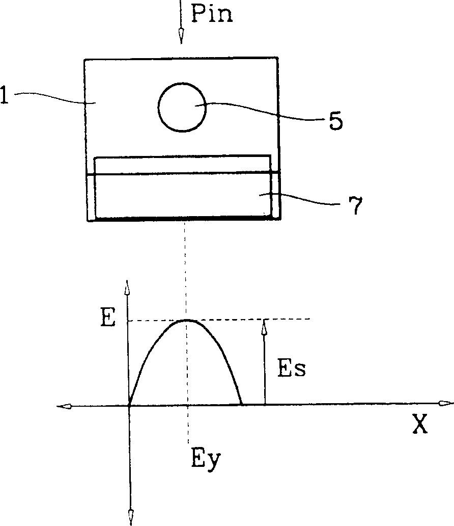
technical field [0001] The present invention relates to a microwave oven, and more particularly to a microwave oven adapted to radiate microwaves in opposite phases to each other to minimize the change in impedance of a waveguide in response to changes in food load, thereby maintaining the microwave at a constant rate regardless of the amount of food load. value output while keeping the distribution of the electric field in the cavity constant. Background technique [0002] Generally, a microwave oven is used to radiate microwaves generated by magnetron vibration into the cavity through a waveguide, so as to heat and cook food placed in a predetermined position in the cavity through dielectric heating. [0003] figure 1 is a schematic cross-sectional view of a waveguide in a microwave oven according to an embodiment of the present invention, figure 2 for figure 1 Analysis diagram of the radiation structure of the medium waveguide, wherein the waveguide 1 is formed with a...

Claims


Application Information

Patent Timeline
IPC IPC(8): F24C7/02H05B6/64H01P7/06
Inventor 金泰凤朱起勋辛钟燮李应燮
Owner SAMSUNG ELECTRONICS CO LTD
Learn More