
Aero-engine turbine blade surface product layer analysis method

A technology for aero-engines and turbine blades, which is applied to the analysis of materials, material analysis using wave/particle radiation, and measurement devices, etc. It can solve the problems of poor usability of turbine blade cutting machines, large affected areas, and different depths of product layers, etc., to achieve Diversified analysis methods, improved integrity, and high work efficiency

Active Publication Date: 2020-08-04
AECC SHENYANG ENGINE RES INST
View PDF26 Cites 2 Cited by
  • Summary
  • Abstract
  • Description
  • Claims
  • Application Information

AI Technical Summary

Problems solved by technology

[0003] In the prior art, there are generally the following disadvantages when analyzing the product layer of aero-engine turbine blades: the turbine blade cutting machine has poor usability, the thickness of the grinding wheel is large, the influence area is large, the precision is not high, and the wire electric discharge machine cannot cut and conduct electricity. Turbine blades sprayed with a protective coating; in the process of preparing metallographic samples to analyze the composition and depth of the product layer, the loose and porous product layer will be worn when grinding the metallographic sample, making the composition of the product layer In the process of preparing the metallographic sample to analyze the depth of the product layer, the mounting material and the surface of the product layer are connected to each other. Since the non-metallic mounting material will produce a discharge phenomenon in the scanning electron microscope, the depth of the product layer will be affected. The analysis is affected; different corrosion environments have different degrees of corrosion on different parts of the same turbine blade, resulting in different depths of the product layer, which cannot effectively evaluate the depth of the corrosion layer

Method used


Image

  • Aero-engine turbine blade surface product layer analysis method
  • Aero-engine turbine blade surface product layer analysis method
  • Aero-engine turbine blade surface product layer analysis method

Examples


Embodiment Construction

[0037] In order to make the purpose, technical solution and advantages of the application more clear, the technical solution in the embodiment of the application will be described in more detail below in conjunction with the drawings in the embodiment of the application. In the drawings, the same or similar reference numerals denote the same or similar elements or elements having the same or similar functions throughout. The described embodiments are some, but not all, embodiments of the application. The embodiments described below by referring to the figures are exemplary, and are intended to explain the present application, and should not be construed as limiting the present application. Based on the embodiments in this application, all other embodiments obtained by persons of ordinary skill in the art without creative efforts fall within the protection scope of this application. Embodiments of the present application will be described in detail below in conjunction with th...


PUM

PropertyMeasurementUnit
thicknessaaaaaaaaaa

Abstract

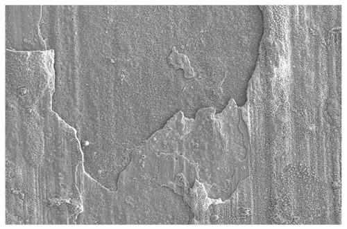
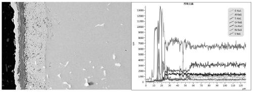
The invention belongs to the field of aero-engines, and particularly relates to an aero-engine turbine blade surface product layer analysis method. The method comprises the following steps: obtaininga cutting sample, making a part of the cutting sample into a metallographic sample, and carrying out morphology and component analysis on the cutting sample and the metallographic sample by using a scanning electron microscope; and carrying out phase analysis on the cutting sample and the metallographic sample by using an X-ray diffractometer, and measuring an average depth of a product layer of the metallographic sample by using a video microscope. Blades are cut through a diamond wire cutting machine, an influence on the product layer is small, and integrity of the product layer is improved;nickel plating protection is performed on the blade product layer so that losses of the product layer in a polishing and grinding process are greatly prevented, and the influence of an inlay on depthmeasurement of the product layer is also prevented; and instruments such as the scanning electron microscope, the X-ray diffractometer and the video microscope are combined to comprehensively analyzemorphology, a phase, components and a depth of the product layer so that efficiency is high, and guidance is good.

Description

technical field [0001] The application belongs to the field of aero-engines, and in particular relates to a method for analyzing a product layer on the surface of an aero-engine turbine blade. Background technique [0002] Turbine blades are an important part of the turbine section. The high-speed rotating blades are responsible for sucking high-temperature and high-pressure air into the combustor to maintain the engine's work. Turbine blades generally bear greater working stress, higher operating temperature and denser gas environment. In order to ensure stable and long-term operation in the extreme environment of high temperature, high pressure and high gas, turbine blades often adopt different methods such as internal airflow cooling , Boundary surface cooling, spraying thermal barrier coating and other methods to ensure the reliability of operation. Spraying thermal barrier coating is the most effective protection method at this stage. Thermal barrier coating is a layer...

Claims


Application Information

Patent Timeline
Patent Type & Authority Applications(China)
IPC IPC(8): G01N23/2251G01N23/2202G01N23/207G01N23/20008G01B11/22
CPCG01N23/2251G01N23/2202G01N23/207G01N23/2005G01B11/22
Inventor 李艳明刘欢韩振宇李青王全
Owner AECC SHENYANG ENGINE RES INST
Learn More