Grating preparation method and grating
A technology of grating and cutting direction, applied in diffraction grating, optics, optical components and other directions, can solve problems such as poor grating stability
- Summary
- Abstract
- Description
- Claims
- Application Information
AI Technical Summary
Problems solved by technology
Method used
Image
Examples
Embodiment 1
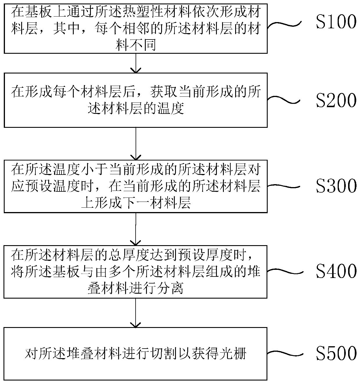
[0072] Please refer to figure 2 , the grating preparation method is applied to a grating preparation device, the grating preparation device includes a substrate, and the grating preparation method includes:
[0073] S100, sequentially forming material layers on the substrate through thermoplastic materials, wherein the materials of each adjacent material layer are different;
[0074] Among them, thermoplastics are plastics that are plastic at a certain temperature, solidify after cooling, and can repeat this process. The grating preparation device forms the material layer on the substrate by spraying or coating.
[0075] Wherein, since the Bragg grating is alternately composed of materials with different refractive indices, in order to meet the performance requirements of the prepared grating, the refractive index of the first material is not equal to the refractive index of the second material. In a specific embodiment, the The grating is composed of two thermoplastic mate...
Embodiment 2
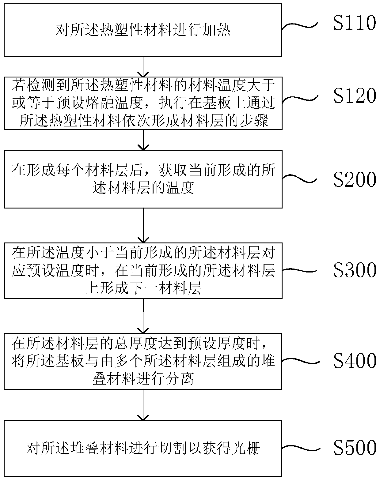
[0085] Please refer to image 3 , in Embodiment 1, the above step S100 includes:
[0086] S110, heating the thermoplastic material;
[0087] S120, if it is detected that the material temperature of the thermoplastic material is greater than or equal to a preset melting temperature, sequentially forming material layers with the thermoplastic material.
[0088] Wherein, when the thermoplastic material is sprayed or coated to form the material layer on the substrate, in order to ensure the fluidity of the thermoplastic material, it is necessary to first heat the thermoplastic material to the corresponding melting temperature, After the thermoplastic material is melted into a liquid, the thermoplastic material is sprayed or coated.
[0089] Specifically, when it is detected that the material temperature of the thermoplastic material is greater than the preset melting temperature, the thermoplastic material is in a liquid state, and the thermoplastic material is in a flowable liq...
Embodiment 3
[0093] Please refer to Figure 4 , in Embodiment 1, the above step S500 includes:
[0094] S510, stretching the stacked material;
[0095] Wherein, after the stacked material is formed by alternately coating the first material layer and the second material layer, due to the large size requirements of different gratings, and the thickness of the stacked material cannot completely conform to the thickness of the grating. Therefore, the stacked material can be stretched to change the thickness of the stacked material, thereby facilitating the preparation of the grating. Specifically, the stretching operation can be performed on the stacked material by a stretching device, the stretching device includes clamping mechanisms arranged oppositely, the two clamping mechanisms clamp the two side edges of the stacked material, and moving in directions away from each other, so as to drive the deformation of the stacked material and change the thickness of the stacked material.
[0096]...
PUM
| Property | Measurement | Unit |
|---|---|---|
| glass transition temperature | aaaaa | aaaaa |
| temperature | aaaaa | aaaaa |
| thickness | aaaaa | aaaaa |
Abstract
Description
Claims
Application Information
 - R&D Engineer
- R&D Manager
- IP Professional
- Industry Leading Data Capabilities
- Powerful AI technology
- Patent DNA Extraction
Browse by: Latest US Patents, China's latest patents, Technical Efficacy Thesaurus, Application Domain, Technology Topic, Popular Technical Reports.
© 2024 PatSnap. All rights reserved.Legal|Privacy policy|Modern Slavery Act Transparency Statement|Sitemap|About US| Contact US: help@patsnap.com


