
Fine stamping process method of compressor intermediate plate

A process method and compressor technology, applied in the field of compressors, can solve problems such as low efficiency, difficulty in ensuring reliable and stable finished product forming, unfavorable energy conservation and environmental protection, etc.

Pending Publication Date: 2020-07-07
FOSHAN NUODI PRECISION MOLD CO LTD
View PDF0 Cites 3 Cited by
  • Summary
  • Abstract
  • Description
  • Claims
  • Application Information

AI Technical Summary

Problems solved by technology

It is difficult to meet these precision requirements by using conventional machining technology. In order to meet the above requirements, traditional forging technology is often used for the manufacture of compressor intermediate plates. The whole process is as follows: material preparation→heating→die forging→turning the outer circle→drilling 9 pieces Hole→double-sided grinding→heat treatment→cleaning→correction→full inspection and packaging
The traditional forging process for the middle plate of the compressor has the following defects: (1) There are many processing steps, and the processing process is relatively complicated; (2) The hole and the shape are processed separately, and due to the need for secondary positioning, the accumulated error causes the hole position Poor dimensional stability, coupled with the fact that the minimum hole margin of φ7 and φ9 is only 2.7 mm, it is more difficult to form, the scrap rate is high, and it is difficult to ensure the reliability and stability of finished product forming; (3) The consumption of materials and energy is large, which is not conducive to energy conservation and environmental protection , leading to high production costs and low efficiency

Method used


Image

  • Fine stamping process method of compressor intermediate plate
  • Fine stamping process method of compressor intermediate plate
  • Fine stamping process method of compressor intermediate plate

Examples


Embodiment Construction

[0096] The present invention and its beneficial technical effects will be further described in detail below in conjunction with the accompanying drawings and preferred embodiments. In order to facilitate the distinction during explanation, bolts in the prior art are generally used for “detachable setting”; some similar technical features are divided according to their commonly used size specifications, such as “φ” for diameters and specific numerical values ​​are explained. In practical applications, the corresponding numerical values ​​can be adjusted according to actual needs, and are not fixed. Other components with independent action control that are not specifically described can be driven by conventional methods such as air cylinders and oil cylinders on the punching machine.

[0097] see Figure 27 , the fine blanking process method of the compressor intermediate plate body preferably implemented in the present invention is characterized in that it includes the followi...


PUM


Abstract

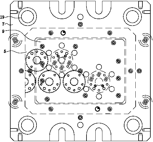
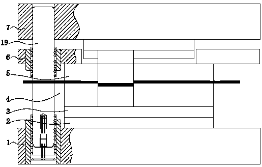
The invention discloses a fine stamping process method of a compressor intermediate plate blank. The method is characterized by comprising the following processes of material preparation, stamping, external circle turning, small hole drilling, double-face grinding, cleaning and full inspection packaging. The fine stamping process adopts a special composite die, the special composite die comprisesan upper die assembly and a lower die assembly which are oppositely arranged up and down, and the upper die assembly and the lower die assembly both adopt a relatively scientific and reasonable structure to realize synchronous machining of key holes and shapes. The method has the advantages that two processes of heating and correcting are saved, the machining amount of seven holes is reduced in the drilling process, the machining process is greatly reduced and simplified, the production cost is reduced, the efficiency is improved, and the product quality is improved; the key holes and the shapes are synchronously machined, secondary positioning is not needed, accumulated errors are avoided, the shape and position sizes are more stable, and the yield of products is greatly improved; the consumption of materials and energy is greatly reduced, energy is saved, and the environment is protected; and the problems that the edge distance of phi7 and phi 9 holes is small and forming is difficult are solved.

Description

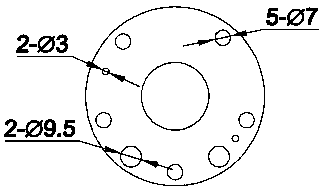
technical field [0001] The invention relates to the technical field of compressors, in particular to the processing technology of a compressor intermediate plate. Background technique [0002] The middle plate of the compressor is generally a circular structure or a quasi-circular structure, which is commonly used in the compressors of air conditioners and large freezers. Such as figure 1 As shown, the middle plate of the compressor is generally a cylindrical structure, and there is a φ31.2 hole in the middle of the axial direction, and there are several holes around the φ31.2 hole near the edge of the compressor middle plate, such as five φ7 holes, 2 φ9.5 holes, 2 φ3 holes, the distance between these holes and the edge of the compressor middle plate is at least 2.7 mm, and the size error range of the hole position is required to be less than 0.2mm, and the vertical size error range is required to be less than 0.1 mm, the accuracy requirements are relatively high; and due ...

Claims


Application Information

Patent Timeline
IPC IPC(8): B21D37/12B21D35/00B23P15/00
CPCB21D35/001B21D35/002B21D37/12B23P15/00
Inventor 芮小勇
Owner FOSHAN NUODI PRECISION MOLD CO LTD
Learn More