A carbon film deposition device

A deposition device and carbon film technology are applied in the field of metal surface treatment to achieve the effects of good wear resistance, improved deposition efficiency and small internal stress

Active Publication Date: 2022-03-22
珠海凯赛奥表面技术有限公司
View PDF7 Cites 0 Cited by
  • Summary
  • Abstract
  • Description
  • Claims
  • Application Information

AI Technical Summary

Problems solved by technology

[0005] The present invention aims to solve the problems described above

Method used


Image

  • A carbon film deposition device
  • A carbon film deposition device

Examples


Embodiment Construction

[0028] In order to make the purpose, technical solutions and advantages of the embodiments of the present invention clearer, the technical solutions of the present invention will be clearly and completely described below in conjunction with the embodiments of the present invention. Obviously, the described embodiments are part of the embodiments of the present invention , but not all examples. Based on the embodiments of the present invention, all other embodiments obtained by persons of ordinary skill in the art without making creative efforts belong to the protection scope of the present invention. It should be noted that, in the case of no conflict, the embodiments in the present application and the features in the embodiments can be combined arbitrarily with each other.

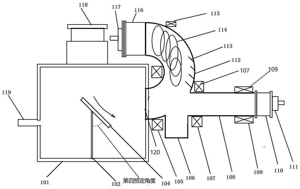
[0029] Such as figure 1 As shown, a carbon film deposition device includes: a vacuum chamber 101, a vacuum device 118 arranged on the top of the vacuum chamber 101 for providing a vacuum for the vacuum c...


PUM

PropertyMeasurementUnit
lengthaaaaaaaaaa

Abstract

The invention provides a carbon film deposition device, comprising: a vacuum chamber, a vacuum device arranged on the top of the vacuum chamber, a magnetic filter device arranged on one side of the vacuum chamber, and a side of the vacuum chamber opposite to the magnetic filter device There is an air inlet on the side. The magnetic filtering device includes a magnetic filtering elbow, a magnetic filtering straight pipe connected to the magnetic filtering elbow, a focusing magnetic field arranged outside the magnetic filtering elbow, and a high-frequency magnetic field arranged outside the magnetic filtering straight pipe. The magnetic filter elbow is coupled to the magnetic filter straight pipe at a first predetermined angle; the magnetic filter straight pipe is connected to the first anode cylinder, and the first anode cylinder is provided with a first cathode sleeve; the magnetic filter elbow is connected to the second anode cylinder, A second cathode sleeve is provided outside the second anode sleeve; the second cathode material in the second cathode sleeve is carbon. The magnetic filter straight pipe of the carbon film depositing device of the present invention is coupled with the magnetic filter bend pipe, and the deposited carbon film has small internal stress, almost no carbon particles, and high hardness of the film layer.

Description

technical field [0001] The invention belongs to the technical field of metal surface treatment, in particular to a deposition device for depositing a carbon film on a PCB cutter. Background technique [0002] In recent years, the rapid development of the PCB industry has not only led to a rapid increase in the output of cemented carbide micro-tools, but also put forward higher requirements for the performance of micro-tools for PCB processing, especially the requirements for service life. The PCB board is composed of multi-layer copper foil wiring, glass fiber and epoxy resin. During the high-speed processing of the PCB board, the high-hardness glass fiber will cause rapid wear of the carbide micro-tools, and the resin at high temperature will also Strong chemical corrosion is formed on the binder phase Co in cemented carbide. Therefore, the lifespan of micro tools made of cemented carbide materials is very short when processing PCB boards, and in order to meet the precisio...

Claims


Application Information

Patent Timeline
Patent Type & Authority Patents(China)
IPC IPC(8): C23C14/06C23C14/32C23C14/14
CPCC23C14/0605C23C14/325C23C14/0635C23C14/0021C23C14/14
Inventor 程文雅
Owner 珠海凯赛奥表面技术有限公司
Why Eureka
Try Eureka