Manufacturing method of field oxide with gradually changed thickness in trench and manufacturing method of SGT device

A manufacturing method and groove technology, applied in the direction of semiconductor devices, semiconductor/solid-state device manufacturing, electrical components, etc., can solve the problems that the electric field distribution cannot be flattened, the electric field strength cannot be pulled up, and the BV effect cannot be maximized, etc., to achieve improvement The effect of breakdown voltage and uniform longitudinal distribution

Active Publication Date: 2020-05-08
HUA HONG SEMICON WUXI LTD
View PDF4 Cites 5 Cited by
  • Summary
  • Abstract
  • Description
  • Claims
  • Application Information

AI Technical Summary

Problems solved by technology

[0018] However, in reality, because of the voltage drop on the source polysilicon 105, the potential decreases from deep to shallow. Although the electric field intensity at the bottom of the trench can be raised, the entire electric field distribution cannot be leveled, and the effect of increasing BV cannot be maximized.
like figure 2 shown, is figure 1 The simulation diagram of the shown device and the corresponding electric field intensity distribution simulation curve; curve 201 is the electric field intensity distribution curve along the dotted line AA, and curve 202 is the electric field intensity distribution curve along the dotted line BB, as can be seen, the electric field intensity at the dotted line AA place is higher Large, at the bottom of the trench 103, there will be a peak electric field intensity as shown by the dotted circle 203, but the electric field intensity in the area shown by the dotted circle 204 cannot be pulled up, so the effect of increasing BV cannot be maximized

Method used


Image

  • Manufacturing method of field oxide with gradually changed thickness in trench and manufacturing method of SGT device
  • Manufacturing method of field oxide with gradually changed thickness in trench and manufacturing method of SGT device
  • Manufacturing method of field oxide with gradually changed thickness in trench and manufacturing method of SGT device

Examples


Embodiment Construction

[0066] The manufacturing method of the field oxygen with gradually changing thickness in the trench according to the embodiment of the present invention:

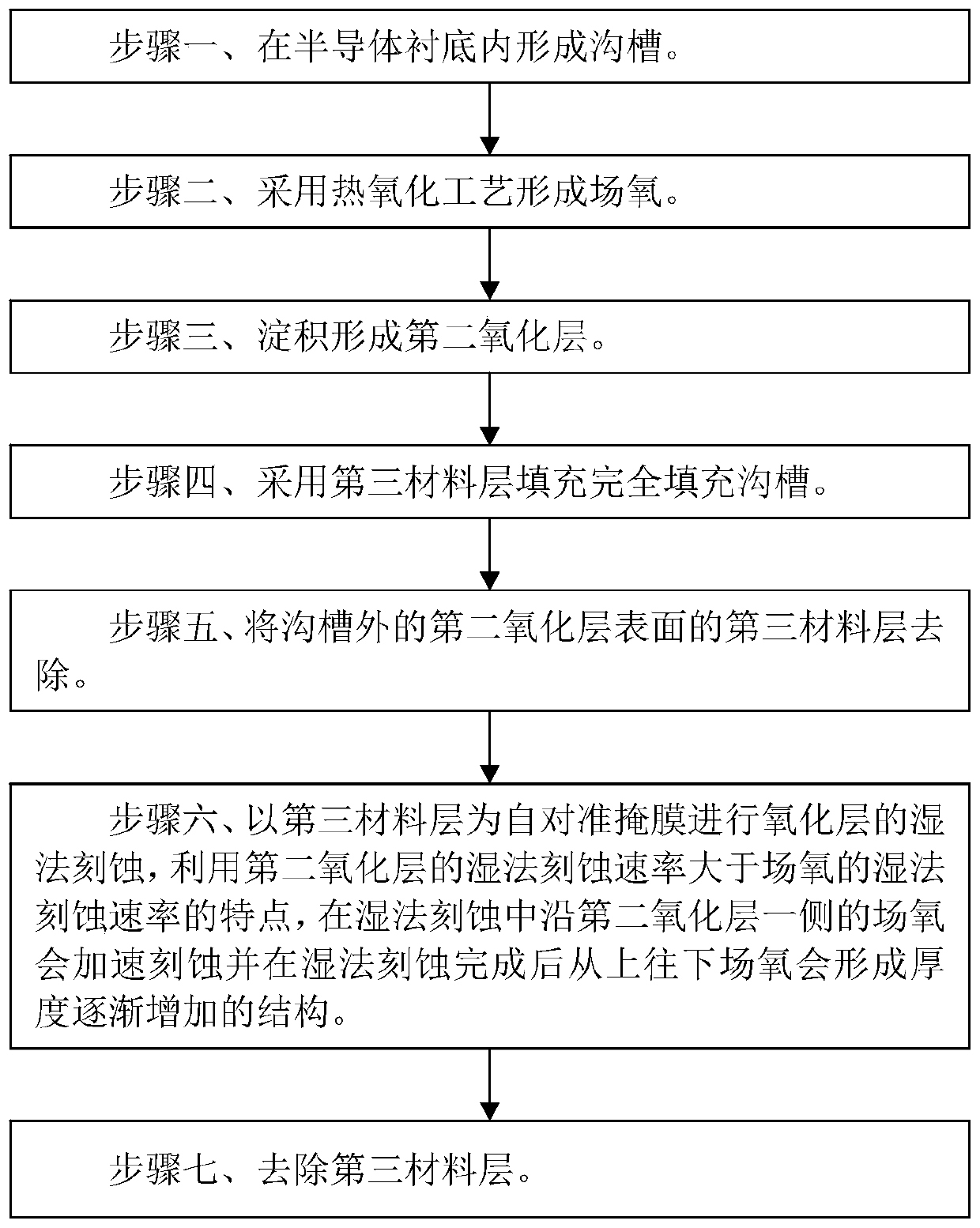
[0067] Such as image 3 Shown is the flow chart of the method for manufacturing field oxygen with gradually changing thickness in the groove of the embodiment of the present invention; as Figure 4A to Figure 4G Shown is a schematic diagram of the device structure in each step of the method for manufacturing field oxygen with gradually changing thickness in the groove of the embodiment of the present invention; the method for manufacturing field oxygen with gradually changing thickness in the groove of the embodiment of the present invention includes the following steps:

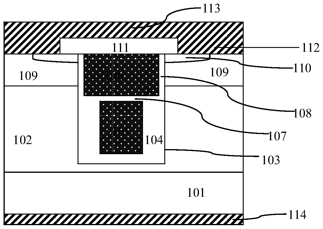
[0068] Step 1, such as Figure 4A As shown, a semiconductor substrate 1 is provided in which a trench 2 is formed.

[0069] The semiconductor substrate 1 is a silicon substrate.

[0070] Usually, the trench 2 has a side slope angle of 87.5°-89°.

[00...


PUM


Abstract

The invention discloses a manufacturing method of field oxide with gradually changed thickness in a trench. The method comprises: a step 1, forming a trench in a semiconductor substrate; a step 2, forming field oxygen by adopting a thermal oxidation process; a step 3, depositing to form a second oxide layer; a step 4, completely filling the trench with a third material layer; a step 5, removing the third material layer on the surface of the second oxide layer outside the trench; a step 6, carrying out wet etching of the oxide layer by taking the third material layer as a self-alignment mask. By utilizing the characteristic that the wet etching rate of the second oxide layer is greater than the wet etching rate of the field oxygen, the field oxygen along one side of the second oxide layer can accelerate etching in the wet etching process and can form a structure with gradually increased thickness from top to bottom after the wet etching is finished; and a step 7, removing the third material layer. The invention further discloses a manufacturing method of the SGT device.

Description

technical field [0001] The invention relates to a method for manufacturing a semiconductor integrated circuit, in particular to a method for manufacturing field oxygen with gradually changing thickness in a trench; Manufacturing method. Background technique [0002] SGT devices such as SGT MOS devices are advanced device structures of ordinary trench gate (Trench) MOS devices, such as figure 1 Shown is a schematic structural diagram of an existing SGT MOS device; taking an N-type device as an example, the existing SGT MOS device includes: [0003] An N-type epitaxial layer (EPI) 102 is formed on the surface of an N+ semiconductor substrate such as a silicon substrate 101 . [0004] The trench 103 is formed in the N-type epitaxial layer 102 . [0005] The gate structure is formed in the trench 103 , including: a bottom dielectric layer 104 , a source polysilicon (source poly) 105 , a polysilicon gate 106 , an interpolysilicon dielectric layer 107 and a gate dielectric laye...

Claims


Application Information

Patent Timeline
IPC IPC(8): H01L21/28H01L21/336H01L29/423
CPCH01L29/401H01L29/4236H01L29/42368H01L29/66666H01L21/28211H01L21/28194
Inventor 陈正嵘
Owner HUA HONG SEMICON WUXI LTD
Why Eureka
Try Eureka