
Novel chip packaging body and packaging method thereof

A technology of chip packaging and packaging method, which is applied in the manufacturing of electric solid state devices, semiconductor devices, semiconductor/solid state devices, etc., can solve the problems of increasing the number of leads, high cost, increasing peripheral devices and direct observation of electrical damage, etc., to achieve the production process. Simple and flexible, the effect of avoiding external force damage

Pending Publication Date: 2020-04-28
BEIJING TONGFANG MICROELECTRONICS
View PDF0 Cites 4 Cited by
  • Summary
  • Abstract
  • Description
  • Claims
  • Application Information

AI Technical Summary

Problems solved by technology

[0003] In view of the deficiencies in the above-mentioned prior art, the purpose of the present invention is to provide a novel chip package and its packaging method, the novel chip package includes a base plate, pins and caps, the novel chip package solves the problem of integration The problem of slow speed and high cost of sample preparation in the circuit engineering stage, while increasing the number of leads, realizes low-cost and fast sample capping in the engineering stage, and meets FA-related requirements such as adding peripheral devices and directly observing electrical damage

Method used


Image

  • Novel chip packaging body and packaging method thereof
  • Novel chip packaging body and packaging method thereof
  • Novel chip packaging body and packaging method thereof

Examples


Embodiment Construction

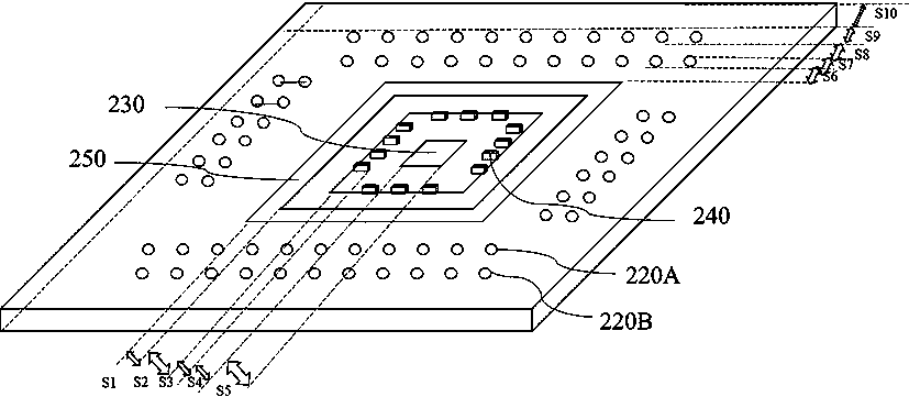
[0030] see figure 2 , a three-dimensional structure diagram of a novel chip package embodied in the present invention. The new chip package includes a base plate 200, pins 300 and a cap 400, wherein the base plate 200 includes a substrate 210, a through hole 220, a well bottom 230, a gold finger 240 and a base step 250; 210 is made of specific phenolic plastic with a thickness of 1.5 mm. There are several through holes 220 on each of the four sides of the substrate 210. The diameter of the through holes is 0.889 mm; the through holes 220 are divided into inner layer through holes 220A and outer layer through holes 220B. The through hole 220A and the outer layer through hole 220B are relatively parallel arranged, the hole spacing between the inner layer through hole 220A and the outer layer through hole 220B is 1.778mm, and the linear distance between the inner layer through hole 220A and the edge of the outer layer through hole 220B is 0.889mm mm, the inner layer through hol...


PUM

PropertyMeasurementUnit
Thicknessaaaaaaaaaa
Lengthaaaaaaaaaa
Lengthaaaaaaaaaa

Abstract

The invention provides a novel chip packaging body and a packaging method thereof. The novel chip packaging body comprises a base plate, insertion pins and a cap; the base plate comprises a substrate,through holes, a well bottom, golden fingers and a base step; and the through holes are divided into inner-layer through holes and outer-layer through holes. The production process of the novel chippackaging body is simple and flexible, is compatible with existing wire bonding environments, and can be used for rapidly preparing a sample at low cost in an engineering stage. The substrate of the novel chip packaging body is made of specific phenolic plastic, so that the substrate has the characteristics of high hardness, high temperature resistance, wear resistance, corrosion resistance, insulation and the like, and is electrically connected with a chip through combining pins. According to the packaging method of the novel chip packaging body, the cap can be directly and manually added, sothat external force-induced damage is avoided; the design of the method meets FA related requirements in the engineering stage; peripheral devices are conveniently added; and electric damage can be directly observed for failure analysis.

Description

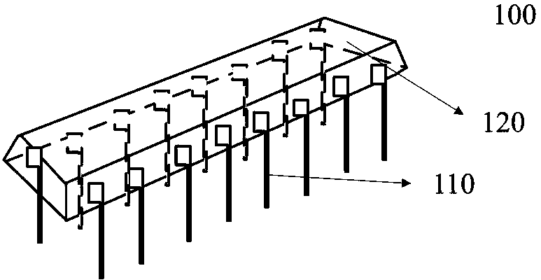
technical field [0001] The invention relates to the technical field of integrated circuit packaging, in particular to a novel chip package and a packaging method thereof. Background technique [0002] Packaging is very important for chips. On the one hand, the chip after reduction needs to be isolated from the outside world to prevent impurities in the air from corroding the chip circuit and causing electrical performance degradation; on the other hand, the packaged chip is also convenient for testing and transportation. . Such as figure 1 As shown, the structure of the existing chip plastic package is shown. The plastic package includes a tube leg 110 and a tube shell 120. The tube leg 110 communicates, and the tube shell 120 can protect the packaging process. There are many forms of packaging, such as DIP, QFP, PGA, BGA, SOP, QFN, etc. In the product engineering stage, most small and medium-scale integrated circuits will adopt dual in-line packaging (DIP packaging) or mo...

Claims


Application Information

Patent Timeline
IPC IPC(8): H01L23/498H01L23/04H01L21/50H01L21/56
CPCH01L21/50H01L21/56H01L23/04H01L23/49827H01L23/49838
Inventor 李秀丽肖金磊欧阳睿许秋林陆小勇刘静刘松
Owner BEIJING TONGFANG MICROELECTRONICS
Learn More