Sintering flue gas synergistic treatment system

A technology of sintering flue gas and flue gas condensation, which is applied in the direction of gas treatment, climate sustainability, and combustion technology mitigation. It can solve the problems of poor system operation stability, low utilization rate of by-products, equipment corrosion, etc., and reduce operating costs. , Long-term stable operation with low energy consumption and small footprint

Pending Publication Date: 2020-03-27
ZHEJIANG TUNA ENVIRONMENTAL SCI & TECH
View PDF0 Cites 2 Cited by
  • Summary
  • Abstract
  • Description
  • Claims
  • Application Information

AI Technical Summary

Problems solved by technology

[0004] Multi-pollutant co-management of sintering flue gas refers to the purpose of comprehensive removal of multiple pollutants through one technology or a combination of multiple technologies, linking and matching coupling of unit links or unit environmental protection equipment, and at the same time solves equipment corrosion and blockage , poor system operation stability, low utilization rate of by-products, etc.

Method used


Image

  • Sintering flue gas synergistic treatment system
  • Sintering flue gas synergistic treatment system
  • Sintering flue gas synergistic treatment system

Examples


Embodiment

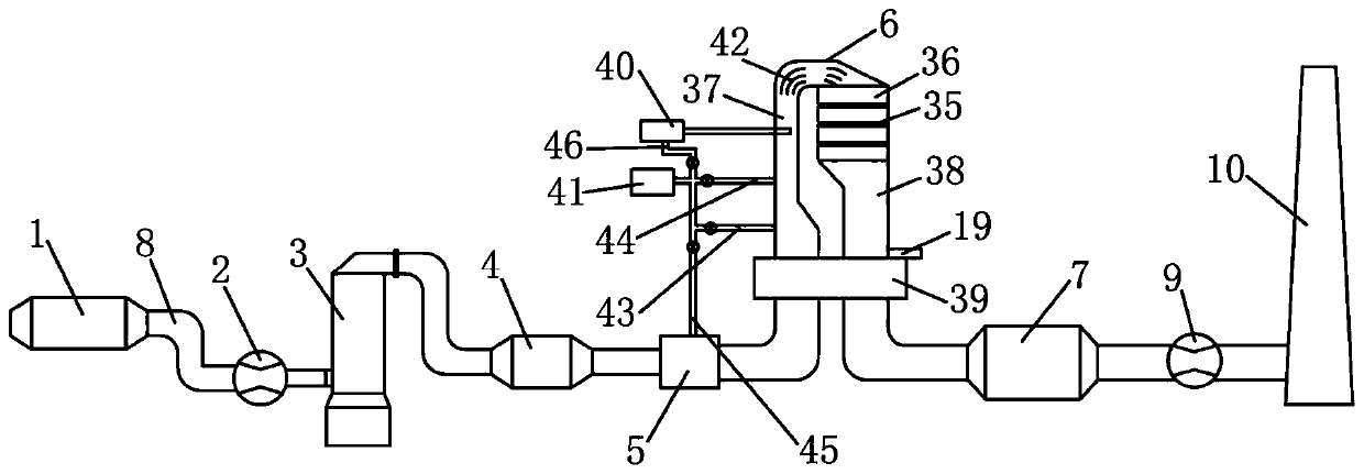
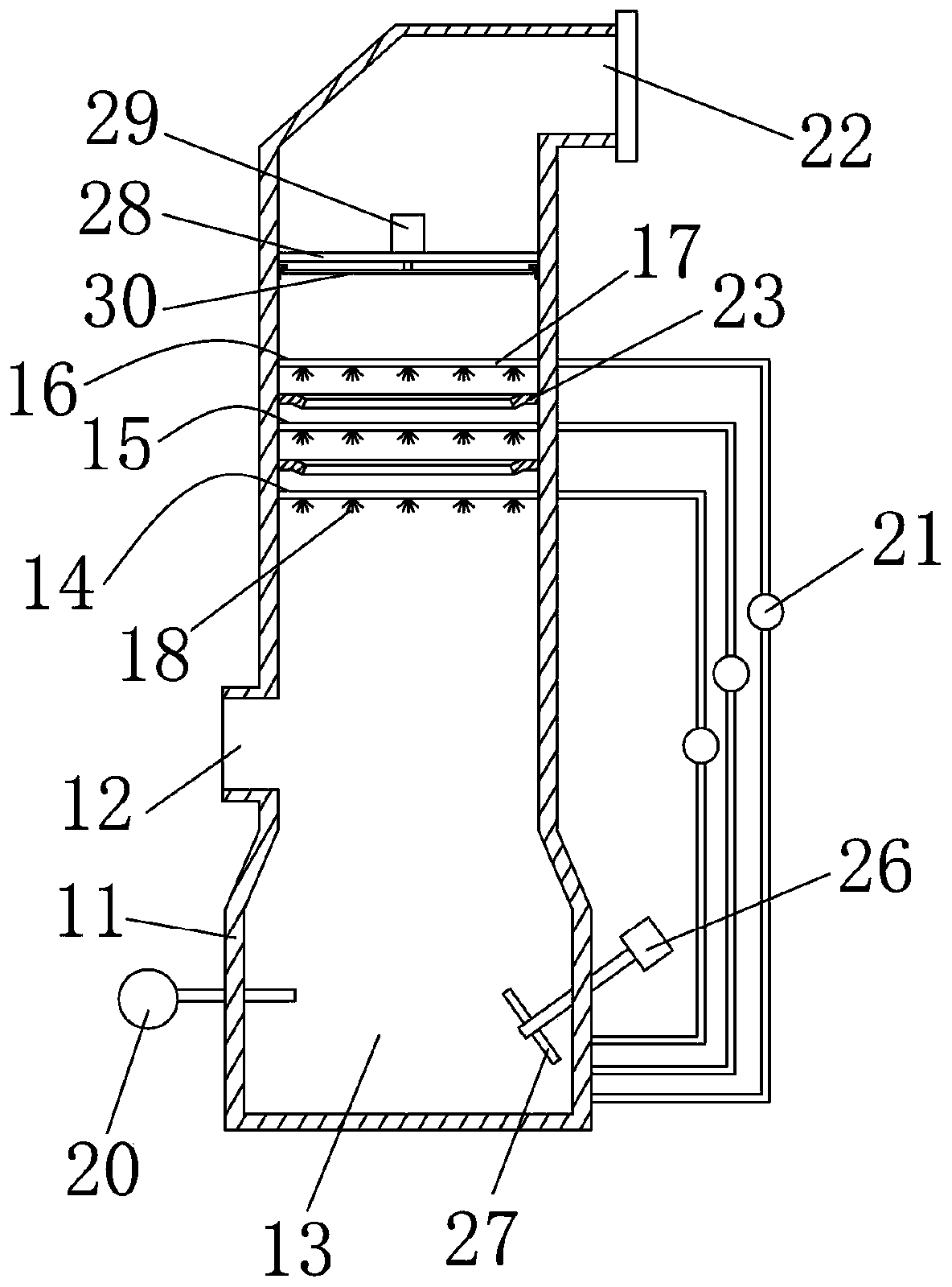
[0027] Embodiment: A kind of sintering flue gas collaborative management system, such as Figure 1-Figure 8 As shown, it includes an electrostatic precipitator 1, a first blower fan 2, a desulfurization device 3, a flue gas condensation dehydrator 4, a flue gas preheater 5, a denitrification device 6, a bag filter 7, a pipeline 8, and a chimney 10 connected to the second blower 9, the electrostatic precipitator 1, the first blower 2, the desulfurization equipment 3, the flue gas condensation water remover 4, the flue gas pre-heater 5, the denitrification equipment 6, the bag filter 7, the second The fan 9 and the chimney 10 are arranged in sequence along the sintering flue gas treatment process, the input end of the electric precipitator 1 is used to feed the sintering flue gas, and the output end of the electric precipitator 1 is input through the pipeline 8 and the first fan 2 The output end of the first fan 2 is connected to the input end of the desulfurization equipment 3 ...


PUM


Abstract

The invention discloses a sintering flue gas synergistic treatment system, and belongs to the technical field of industrial waste gas treatment. The sintering flue gas synergistic treatment system comprises an electric dust remover, a first fan, desulfurization equipment, a flue gas condensation dehydrator, a flue gas preheater, denitration equipment, a bag-type dust remover, a pipeline and a second fan connected with a chimney, wherein the electric dust remover, the first fan, the desulfurization equipment, the flue gas condensation dehydrator, the flue gas preheater, the denitration equipment, the bag-type dust remover, the second fan and the chimney are sequentially arranged along a sintering flue gas treatment process. Compared with the systems in the prior art, the system is small inoccupied area, low in investment cost and low in corrosivity to all equipment and has high desulfurization, denitrification and dust removal efficiency and enables sulfur dioxide, particulate matter and nitric oxide in the sintering flue gas to meet the ultralow emission standard requirements. The waste heat of the sintering flue gas is efficiently recovered and utilized, energy consumption in thetreatment process is reduced, the operation cost is reduced, long-term stable low-energy-consumption operation can be achieved and high practicability of the sintering flue gas is realized.

Description

technical field [0001] The invention belongs to the technical field of industrial waste gas treatment, and in particular relates to a sintering flue gas collaborative treatment system. Background technique [0002] In industrial production, especially in the working process of chemical plants, steel plants, pharmaceutical plants and oil refineries, a large amount of exhaust gas will be produced. If these exhaust gases are not treated, they will cause acid rain, global warming, smog and other phenomena, which will seriously pollute the environment , endangering human health. [0003] Sintering flue gas is a kind of waste gas, the main pollutants are sulfur dioxide, nitrogen oxides and dust. The emission of sintering flue gas is large and the initial flue gas temperature is low. At present, desulfurization, denitrification and dust removal methods are generally used in China for treatment. At present, there are many desulfurization, denitrification and dust removal processes...

Claims


Application Information

Patent Timeline
Patent Type & Authority Applications(China)
IPC IPC(8): B01D53/80B01D53/50B01D53/86B01D53/56B01D50/00B01D53/26B01D53/00F23J15/06
CPCB01D50/00B01D53/005B01D53/265B01D53/501B01D53/8625B01D2257/80B01D2258/0283F23J15/06Y02E20/30
Inventor 金猛赵博陈洪剑李敬东周伟单慧娜顾一飞
Owner ZHEJIANG TUNA ENVIRONMENTAL SCI & TECH
Why Eureka
Try Eureka