
Aluminum pipe surface resin coating system

A resin coating, aluminum tube technology, applied to the device for coating liquid on the surface, pretreatment surface, coating and other directions, can solve the problems of equipment jitter, unsmooth feeding, and back and forth deviation of the entire line, and reduce the Risk of stretching, reducing risk of bending, reducing the effect of non-conforming products

Inactive Publication Date: 2020-02-18
NINGBO INTELLIGENCE INNOVATIVE MATERIALS TECH CO LTD +1
View PDF0 Cites 2 Cited by
  • Summary
  • Abstract
  • Description
  • Claims
  • Application Information

AI Technical Summary

Problems solved by technology

[0003] On the aluminum tube surface resin coating production line, the coating process usually includes feeding, cleaning, drying, gluing, heating, resin coating, cooling, pulling, and recycling, and the process is carried out by the feeder during the feeding process. Feeding, the current feeder is generally fixed on the ground and will not move, and the material roll on the feeder is large and has a certain thickness. This kind of feeder usually uses a passive feeding method for feeding, because the traction in the front will affect the aluminum tube. With a certain stretching effect, deformation will occur, and the next step in the feeding process needs to reshape the aluminum tube. In the process of reshaping, because the aluminum tube moves back and forth on the tray, the central axis of the aluminum tube is in line with the shape The central axis of the aluminum tube at the center shifted back and forth, which caused the whole line equipment to vibrate, the feeding was not smooth, and the quality and mass production of the resin coating equipment could not be guaranteed.

Method used


Image

  • Aluminum pipe surface resin coating system
  • Aluminum pipe surface resin coating system
  • Aluminum pipe surface resin coating system

Examples


Embodiment Construction

[0041] The present invention will be described in detail below in conjunction with the accompanying drawings.

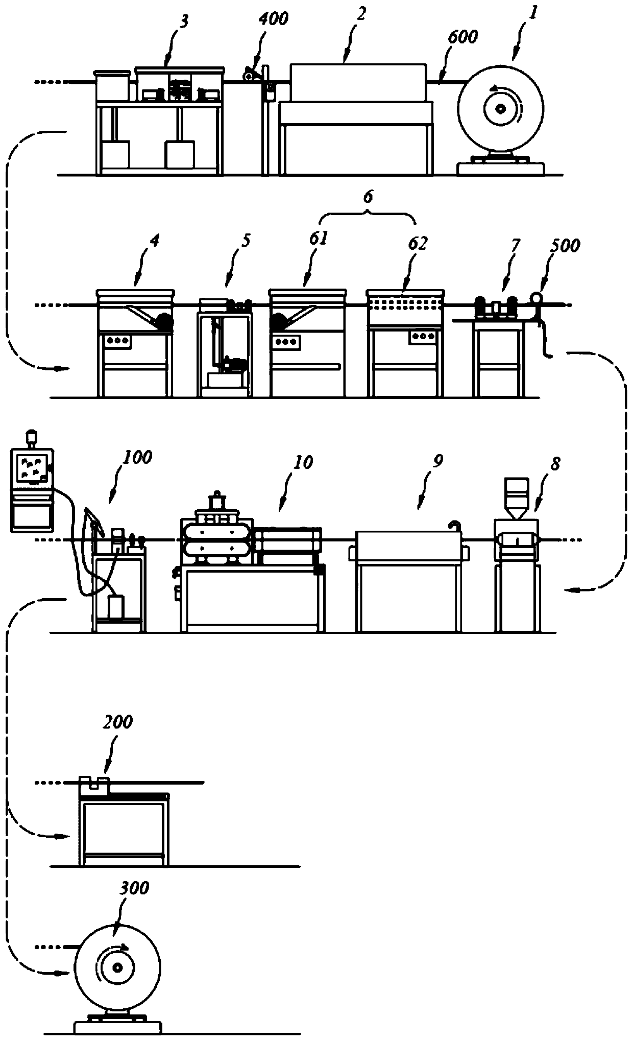
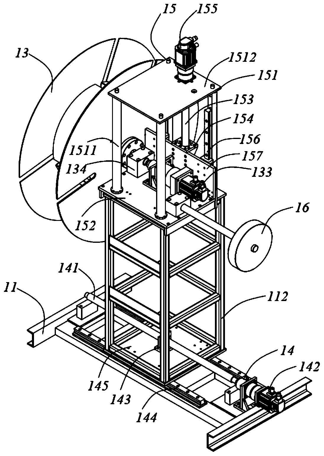
[0042] Such as figure 1The resin coating system on the surface of the aluminum tube is sequentially provided with a discharge unit 1 for outputting the aluminum tube 600, a cleaning unit 3 for cleaning the surface of the aluminum tube 600, and a drying unit for drying the aluminum tube 600 according to the traveling direction of the aluminum tube 600. Surface drying unit 4, glue coating unit 5 for coating glue on the surface of aluminum tube 600, heating unit 6 for heating aluminum tube 600, resin coating unit 8 for coating resin on the surface of aluminum tube 600, The cooling unit 9 for cooling the aluminum tube 600, the traction unit 10 for applying power to the aluminum tube 600 and the collection unit for collecting the aluminum tube 600 are arranged between the discharge unit 1 and the cleaning unit 3 for the aluminum The pipe diameter correction unit 2 for sh...


PUM


Abstract

The invention relates to an aluminum pipe surface resin coating system. A discharging unit, a cleaning unit, a drying unit, a gluing unit, a heating unit, a resin coating unit, a cooling unit, a traction unit and a collecting unit are sequentially arranged in the advancing direction of an aluminum pipe, wherein a pipe diameter correcting unit is arranged between the discharging unit and the cleaning unit; and the discharging unit adjusts the position and speed of the aluminum pipe discharged by the discharging unit according to the position of the aluminum pipe at the pipe diameter correctingunit, so that the aluminum pipe discharged by the discharging unit and the aluminum pipe at the pipe diameter correcting unit are coaxial and the speed is the same. By moving the discharging unit, thecenter axis of the aluminum pipe and the center axis of the aluminum pipe on a production line are coaxial in the discharging process, and the bending risk is reduced; and meanwhile, the dischargingspeed of the aluminum pipe is controlled, the speed of the aluminum pipe in the discharging process and the speed of the aluminum pipe on the production line are kept consistent, the risk that the aluminum pipe is stretched can be reduced, the production quality of the aluminum pipe is improved, and unqualified products are reduced.

Description

technical field [0001] The invention relates to the technology of replacing copper tubes with aluminum tubes in the production and manufacturing industry of condensation tubes, in particular to a resin coating system on the surface of aluminum tubes. Background technique [0002] In daily life and industrial production, air conditioners have become an indispensable electrical appliance. Copper tubes are widely used in air conditioner condensers because of their good thermal conductivity, and copper tubes are relatively expensive metal materials. In order to save costs, in In the field of air-conditioning technology, the use of aluminum tubes instead of copper tubes has attracted more and more attention. [0003] On the aluminum tube surface resin coating production line, the coating process usually includes feeding, cleaning, drying, gluing, heating, resin coating, cooling, pulling, and recycling, and the process is carried out by the feeder during the feeding process. Feed...

Claims


Application Information

Patent Timeline
IPC IPC(8): B05C13/02B05C9/14B05C3/09B05C11/10B05D3/04B08B9/023B21D3/14B21D37/10
CPCB05C3/09B05C9/14B05C11/10B05C11/1039B05C13/02B05D3/0413B08B9/023B21D3/14B21D37/10
Inventor 方林
Owner NINGBO INTELLIGENCE INNOVATIVE MATERIALS TECH CO LTD
Learn More