
A quick-loading and anti-bending tooling for thermally processed camshafts and a quick-loading and anti-bending method

A camshaft and thermal processing technology, applied in metal processing equipment, workpiece cooling devices, manufacturing tools, etc., can solve the problems of environmental and on-site equipment and personnel safety threats, high cost, etc., to improve product yield and turnover efficiency, loading The effect of large capacity and stable loading process

Active Publication Date: 2021-01-01
QILU INST OF TECH
View PDF13 Cites 0 Cited by
  • Summary
  • Abstract
  • Description
  • Claims
  • Application Information

AI Technical Summary

Problems solved by technology

Obviously, the former method adds a new process, and the cost is extremely high. The latter method allows the camshaft to scatter on the ground or the work station. The impact of off-line parts poses a threat to the environment and the safety of on-site equipment and personnel

Method used


Image

  • A quick-loading and anti-bending tooling for thermally processed camshafts and a quick-loading and anti-bending method
  • A quick-loading and anti-bending tooling for thermally processed camshafts and a quick-loading and anti-bending method
  • A quick-loading and anti-bending tooling for thermally processed camshafts and a quick-loading and anti-bending method

Examples


Embodiment 1

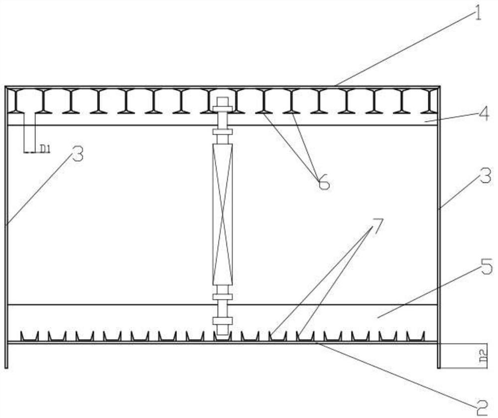
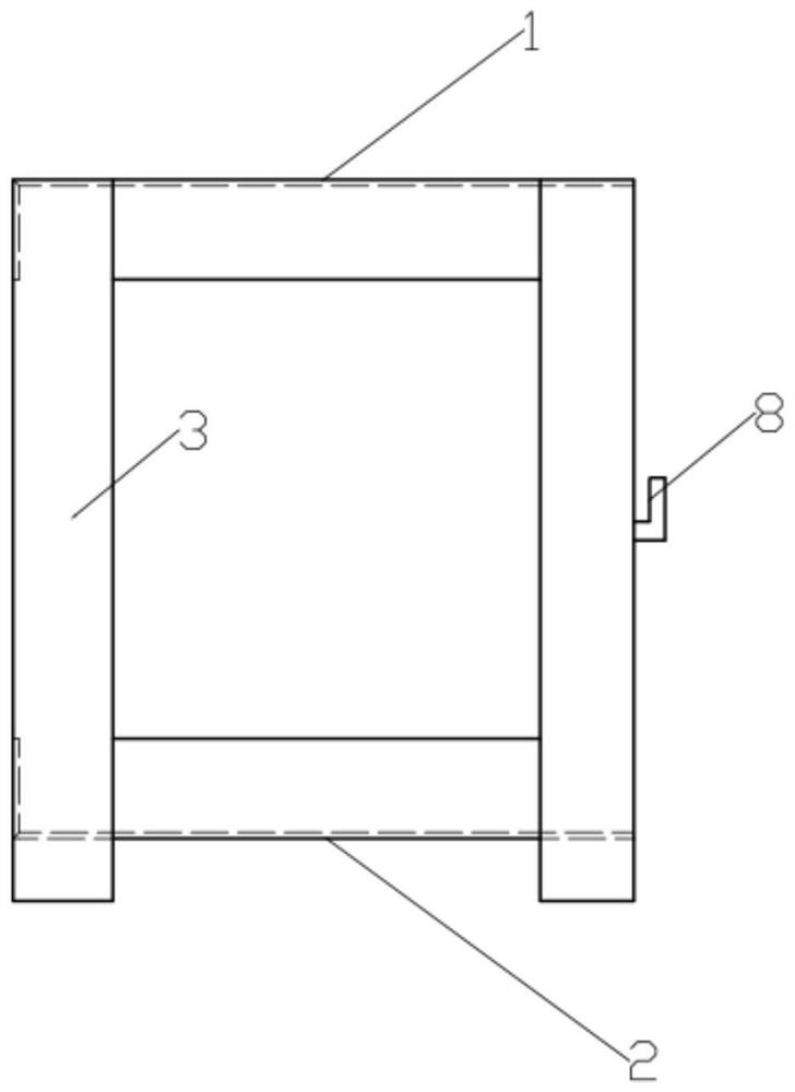
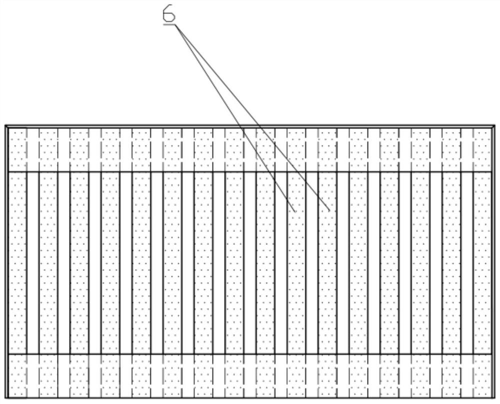
[0032] see Figure 1 ~ Figure 3 , Figure 1 ~ Figure 3 It is a diagram of various directions of a fast loading and anti-bending tooling for a thermally processed camshaft according to Embodiment 1 of the present invention.

[0033] A quick-loading and anti-bending tooling for thermally processed camshafts in this embodiment includes an upper support frame plate 1, a lower support frame plate 2, and a vertical support frame plate 3, and a plurality of the upper support frame plates 1 and lower support frame plates 2 Together with the vertical support frame plate 3, a rectangular parallelepiped frame is formed, and a plurality of I-beams or H-shaped steels 6 are welded on the bottom surface of the upper support frame plate 1. The vertical mode is welded on the bottom of the upper support frame plate 1 through the upper legs, and the plurality of I-beams or H-shaped steels 6 are arranged in parallel and spaced apart, and there is a gap between the edges of the lower legs of two ...

Embodiment 2

[0048] The scheme of embodiment 2 is as Figure 4 As shown, embodiment 2 provides an improved hot-worked camshaft rapid loading anti-bending tooling compared to embodiment 1, the improvement lies in the lower leg of the I-beam or H-beam 6 that will be in direct contact with the red-hot camshaft The part is reinforced, specifically, a reinforcing plate 9 is welded at the bottom end along the width direction of the lower leg, and the reinforcing plate 9 provides a higher resistance to thermal stress deformation for the lower leg of the I-beam or H-shaped steel 6, Ensure the service life of the entire tooling. Other technical features and effects not mentioned in this embodiment may be the same as those in Embodiment 1, and will not be repeated here.


PUM


Abstract

A thermally processed camshaft quick-loading anti-bending tooling, comprising a cube or cuboid frame jointly surrounded by a plurality of upper support frame plates (1), lower support frame plates (2) and vertical support frame plates (3). The bottom surface of the support frame plate (1) is fixedly connected with a plurality of I-beams or H-shaped steels (6), and the top surface of the lower support frame plate (2) is fixedly connected with a plurality of channel steels (7). The red hot camshaft can The gap between two adjacent I-beams or H-beams (6) is loaded and snapped between the lower legs of two adjacent I-beams or H-beams (6), and part of the shaft section at the lower end of the camshaft can Stretch into the gap space between the channel steel (7) two legs. The hot-processed camshaft fast loading anti-bending tooling and corresponding method of the present invention can quickly load the red-hot camshaft, prevent bending caused by traditional horizontal placement and boxing, and have a large capacity, and can quickly calculate the loading amount, comprehensively Improve product yield and turnover efficiency.

Description

technical field [0001] The invention relates to the technical field of shape retention of hot-processed metal parts, in particular to a quick-loading and anti-bending tool for a hot-working camshaft and a quick-loading and anti-bending method. Background technique [0002] The camshaft is an important part of the automobile engine. The camshaft used in the automobile is the finished product after various processes such as blank manufacturing, machining, and surface treatment. The initial camshaft blank is cast or rolled. produced. [0003] We know that the larger the length-to-diameter ratio of metal parts and the higher the temperature, the easier it is to bend and deform. Since the cast camshaft blank is demoulded after cooling, there is generally no problem of loading and bending of the cast camshaft blank, while the rolled camshaft When the shaft comes off the rolling mill (mainly refers to the cross wedge rolling mill), it is in a red-hot state. Immediate packing of th...

Claims


Application Information

Patent Timeline
Patent Type & Authority Patents(China)
IPC IPC(8): B21B39/00B21B45/02
CPCB21B39/002B21B45/0209
Inventor 周爱仙刘淑华
Owner QILU INST OF TECH
Learn More