Thermochromic indicator for reagent gas vessel

An indicator and thermal discoloration technology, applied in the direction of container discharge, gas treatment/storage purpose, installation device of container structure, etc., can solve problems such as damage to equipment or manufactured items, loss of time and productivity, etc.

Pending Publication Date: 2020-02-07
ENTEGRIS INC
View PDF10 Cites 1 Cited by
  • Summary
  • Abstract
  • Description
  • Claims
  • Application Information

AI Technical Summary

Problems solved by technology

In addition to the potential risk of injury or illness to those exposed to the leak and the possibility of damage to equipment or manufactured goods, loss of time and productivity due to work facilities being evacuated due to a hazardous gas release

Method used


Image

  • Thermochromic indicator for reagent gas vessel
  • Thermochromic indicator for reagent gas vessel
  • Thermochromic indicator for reagent gas vessel

Examples


Embodiment Construction

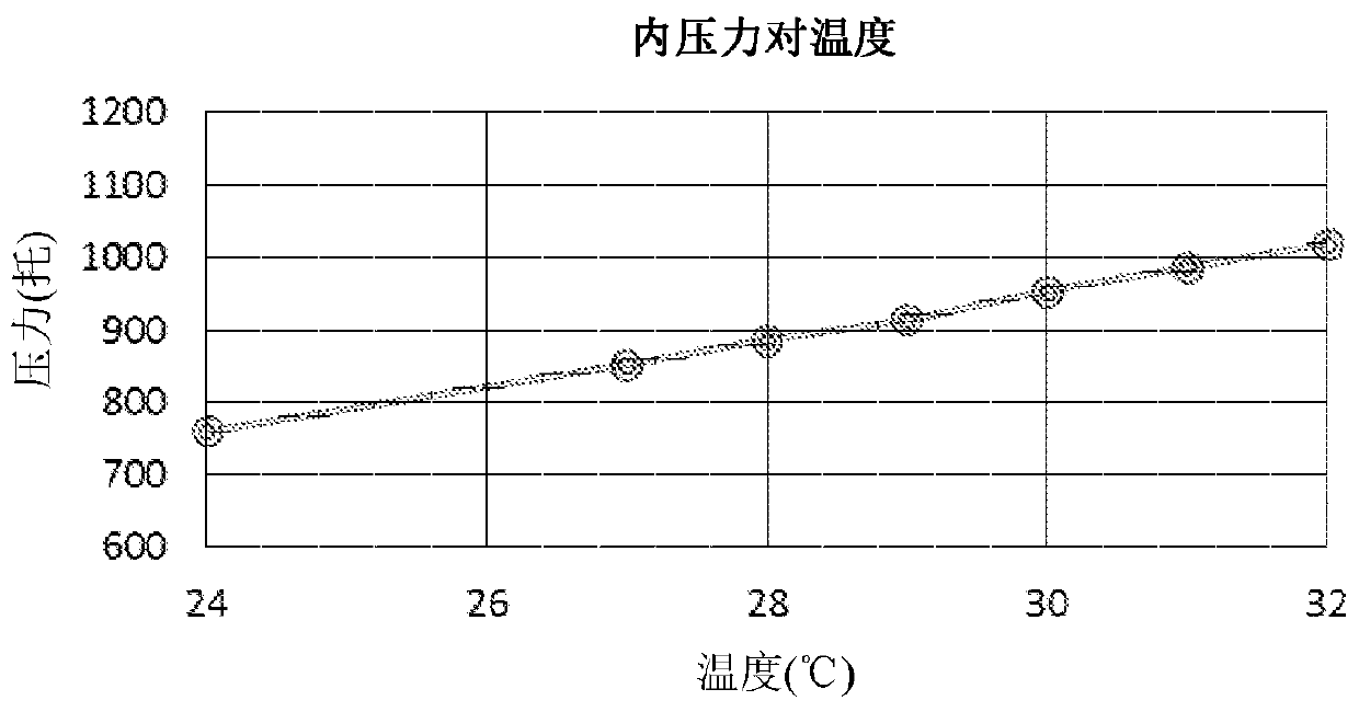
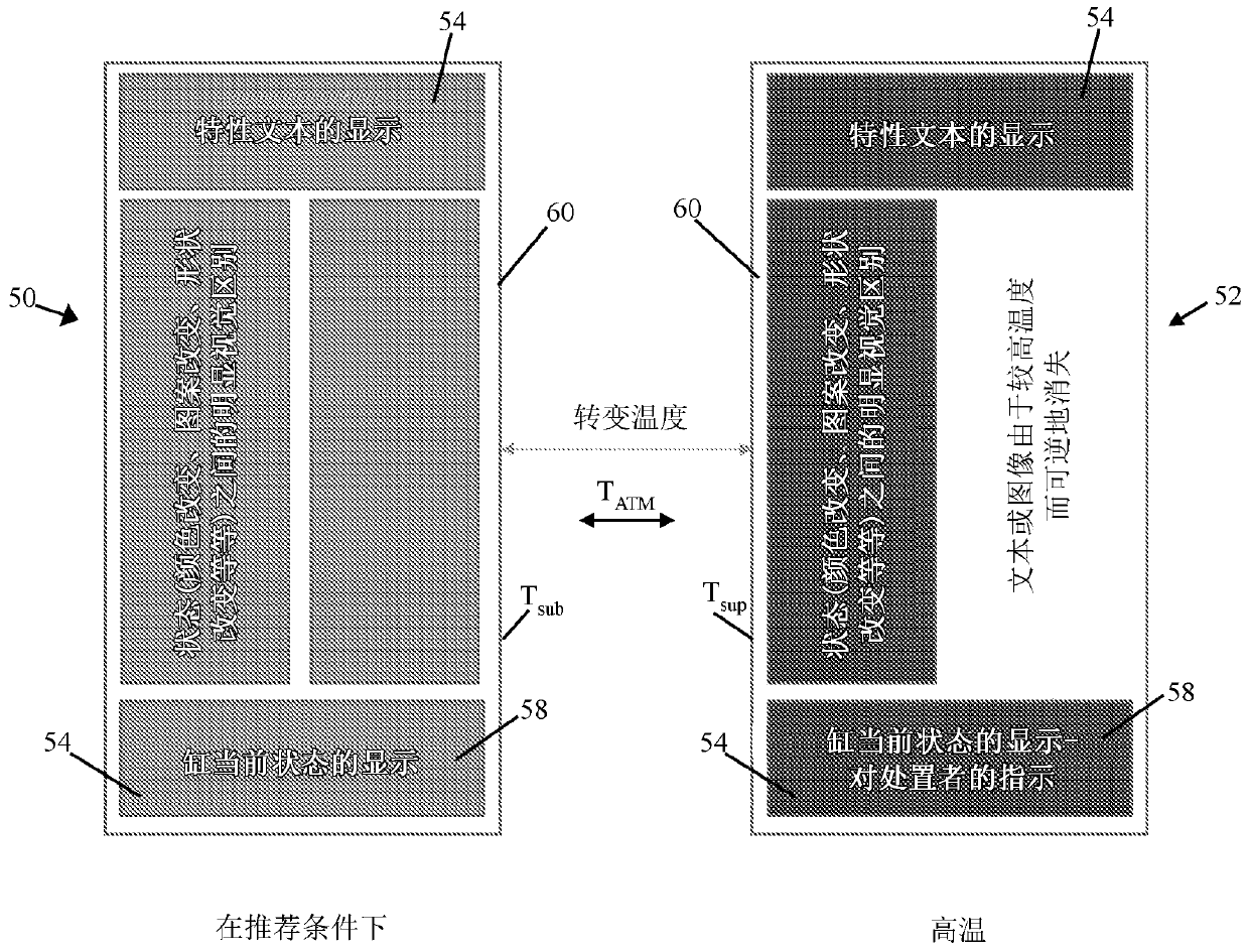
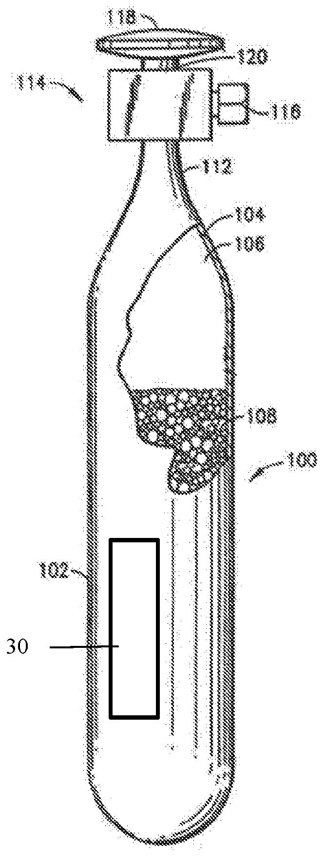
[0031] The present description relates to novel storage containers and methods of use thereof. The container contains a thermochromic indicator effective to communicate information about the pressure of the gaseous contents within the container to a location external to the container. Thermochromic indicators can be used in methods for handling, storing, using, and supplying gases (e.g., hazardous reagent gases) by using a change in appearance to identify whether the pressure of the gas stored in the container exceeds a predetermined maximum pressure, so Said gas is stored by the container with an increased level of safety.

[0032] Gases stored by storage and delivery containers may desirably be stored in said containers, wherein said gas is present at a pressure below a predetermined desired maximum pressure. A predetermined desired maximum pressure is understood to occur at a particular temperature (which may be referred to herein as a "transition temperature", see above)....


PUM


Abstract

A dispensing and storage vessel for use in housing a gas such as toxic and hazardous gas in combination with a temperature sensitive label is described. Example dispensing and storage vessels includean adsorbent and a reagent gas within an internal volume of the vessel. A thermochromic label is adhered to the vessel and communicates temperature-sensitive information in a visual fashion to a user.

Description

[0001] Related applications [0002] This application claims the benefit and priority of U.S. Provisional Application No. 62 / 518,172, filed June 12, 2017, which is hereby incorporated by reference in its entirety for all purposes middle. technical field [0003] The present disclosure relates to indicators for visually conveying information related to the pressure of a reagent gas stored in a container. Background technique [0004] Toxic and other hazardous specialty gases are used in a variety of industrial applications in various manufacturing fields, such as in the manufacture of microelectronics, semiconductors, photovoltaics, and flat panel display products. Examples of specific processes involving hazardous specialty gases as raw materials include those used in ion implantation, epitaxial growth, plasma etching, reactive ion etching, metallization, physical vapor deposition, chemical vapor deposition, optical lithography, Cleaning and doping process. [0005] Vari...

Claims


Application Information

Patent Timeline
Patent Type & Authority Applications(China)
IPC IPC(8): F17C13/02F17C11/00G01K11/12
CPCF17C13/003F17C2205/052F17C13/026G01K11/165G01K11/16F17C2201/0109F17C11/00G01K11/12F17C2250/0439F17C2223/033F17C2260/04F17C2270/05F17C2205/0394F17C2270/0518
Inventor J·德普雷斯E·拉博尔德
Owner ENTEGRIS INC
Why Eureka
Try Eureka