Dielectric medium for wave energy molecular oscillation heat collector
A molecular oscillation and dielectric technology, applied in the field of dielectrics, can solve the problems of air pollution, low power efficiency, smog, etc., and achieve the effect of high electrothermal conversion rate and high heat production efficiency
- Summary
- Abstract
- Description
- Claims
- Application Information
AI Technical Summary
Problems solved by technology
Method used
Image
Examples
Embodiment 1
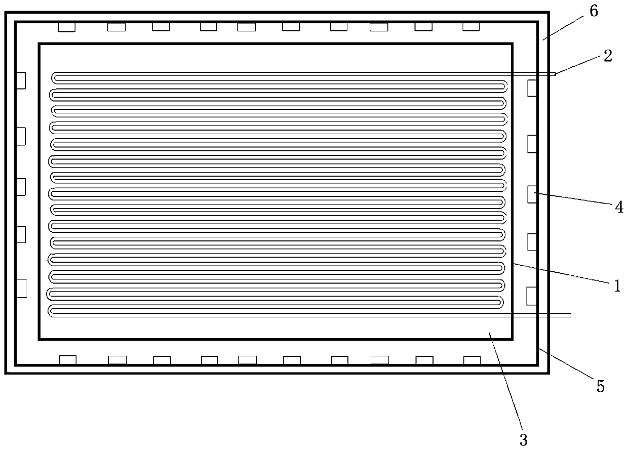
[0036] A wave energy molecular oscillation heat collector, its structure is as follows figure 1 As shown, it includes a dielectric shell 1, a copper serpentine finned metal tube 2, a microwave generator 4, a powdered dielectric 3, a metal shielding shell 5 and an insulation layer 6, wherein the serpentine finned metal tube 2 is installed inside the dielectric shell 1, the powdery dielectric 3 is filled inside the dielectric shell 1, the metal shielding shell 5 is fixed on the outside of the dielectric shell 1, the insulation layer 6 is fixed on the outside of the metal shielding shell 5, and the microwave generator 4. Fixed on the outside of the dielectric shell 1 and the inner wall of the metal shielding shell 5, the powdery dielectric 3 is made of the same material as the dielectric shell 1, including silicon powder and carbon powder, wherein the mass ratio of silicon powder and carbon powder is 4 : 1, wherein, the powdery dielectric 3 has a particle size of 80 meshes and is...
Embodiment 2
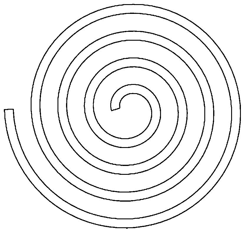
[0039] A wave energy molecular oscillating heat collector, including a dielectric shell, a copper volute-shaped finned metal tube, a microwave generator, a powdered dielectric, a metal shielding shell and an insulation layer, wherein the volute-shaped fin The metal tube is installed inside the dielectric shell, the powdery dielectric is filled inside the dielectric shell, the metal shielding shell is fixed outside the dielectric shell, the insulation layer is fixed outside the metal shielding shell, and the microwave generator is fixed on the metal shielding shell The inner wall of the body, the powdery dielectric and the dielectric shell are made of the same material, including silicon powder and carbon powder, wherein the mass ratio of silicon powder and carbon powder is 2:1, and the particle size of the powdery dielectric is 200 mesh. It is filled inside the dielectric shell; the dielectric shell is sintered at 2100°C by silicon powder and carbon powder. The frequency of th...
Embodiment 3
[0042] A wave energy molecular oscillating heat collector, its structure is a combination of serpentine and helical such as image 3As shown, it includes a dielectric shell 1, a finned metal tube 2, a microwave generator 4, a powdery dielectric 3, a metal shielding shell 5 and an insulation layer 6, and the inlet and outlet are connected to a cooling medium, and the finned metal tube 2 Installed inside the dielectric shell 1, the powdery dielectric 3 is filled inside the dielectric shell 1, the metal shielding shell 5 is fixed on the outside of the dielectric shell 1, the insulation layer 6 is fixed on the outside of the metal shielding shell 5, and the microwave generator 4 Fixed on the inner wall of the metal shielding shell 5, the powdery dielectric 3 is made of the same material as the dielectric shell 1, including silicon powder and carbon powder, wherein the mass ratio of silicon powder and carbon powder is 4:1, wherein the powdery The particle size of the dielectric 3 i...
PUM
| Property | Measurement | Unit |
|---|---|---|
| Particle size | aaaaa | aaaaa |
| Particle size | aaaaa | aaaaa |
Abstract
Description
Claims
Application Information
 - R&D
- Intellectual Property
- Life Sciences
- Materials
- Tech Scout
- Unparalleled Data Quality
- Higher Quality Content
- 60% Fewer Hallucinations
Browse by: Latest US Patents, China's latest patents, Technical Efficacy Thesaurus, Application Domain, Technology Topic, Popular Technical Reports.
© 2025 PatSnap. All rights reserved.Legal|Privacy policy|Modern Slavery Act Transparency Statement|Sitemap|About US| Contact US: help@patsnap.com


