Liquid hazardous chemical substance leakage bridge deck sensing detection early-warning device

A technology of inductive detection and early warning device, applied in material resistance, signal transmission system, instruments, etc., can solve the problems of delay, difficult to repair and replace, and difficult to realize the method of drainage pipeline detection, and achieves the benefits of application promotion, installation and replacement. The effect of easy maintenance

Pending Publication Date: 2019-12-24
ZHEJIANG UNIV OF TECH
View PDF0 Cites 0 Cited by
  • Summary
  • Abstract
  • Description
  • Claims
  • Application Information

AI Technical Summary

Problems solved by technology

[0003] Most of the currently designed bridge deck runoff detection systems for highway bridges are installed in the pipeline below the discharge outlet. The existing deficiencies in the bridge deck runoff detection devices are: 1. Bridge load-bearing, span length, driving Due to reasons such as safety, the capacity of the collection pool, and the construction site of the collection pool, it is impossible to install the bridge deck runoff collection device, so that the bridge deck runoff is all in a "straight discharge" method, so it is difficult to realize the detection method in the drainage pipe
2. In view of the direct discharge method of the cross-river and sea-crossing bridge, it is difficult to install the liquid detection devices for hazardous chemicals in the detection pool and collection pool. Sufficient volume to accommodate possible hazardous material spills
If the collection pool is not emptied in time, the collection pool loses its collection meaning
3. The current bridge deck runoff collection system is not easy to repair and replace
4. The leakage of hazardous chemicals cannot be detected immediately on the bridge deck, which is delayed and poses a safety hazard

Method used


Image

  • Liquid hazardous chemical substance leakage bridge deck sensing detection early-warning device
  • Liquid hazardous chemical substance leakage bridge deck sensing detection early-warning device
  • Liquid hazardous chemical substance leakage bridge deck sensing detection early-warning device

Examples


Embodiment Construction

[0020] The above solution will be further described below in conjunction with specific embodiments. These examples are provided to illustrate the present invention and not to limit the scope of the present invention.

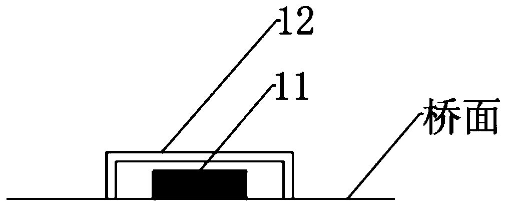
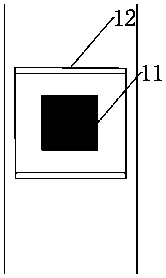
[0021] As shown in FIG. 1 , the bridge deck induction detection and early warning device for leakage of liquid hazardous chemicals according to the present invention includes a primary detection and early warning unit 1 and a secondary detection and early warning unit 2;

[0022] The primary detection and early warning unit 1 includes a liquid dielectric constant detection sensor 11, a first storage module pre-stored with normal rain and snow dielectric constant index values, a first CPU processing module, a first wireless communication module and a first protective shell 12 ;

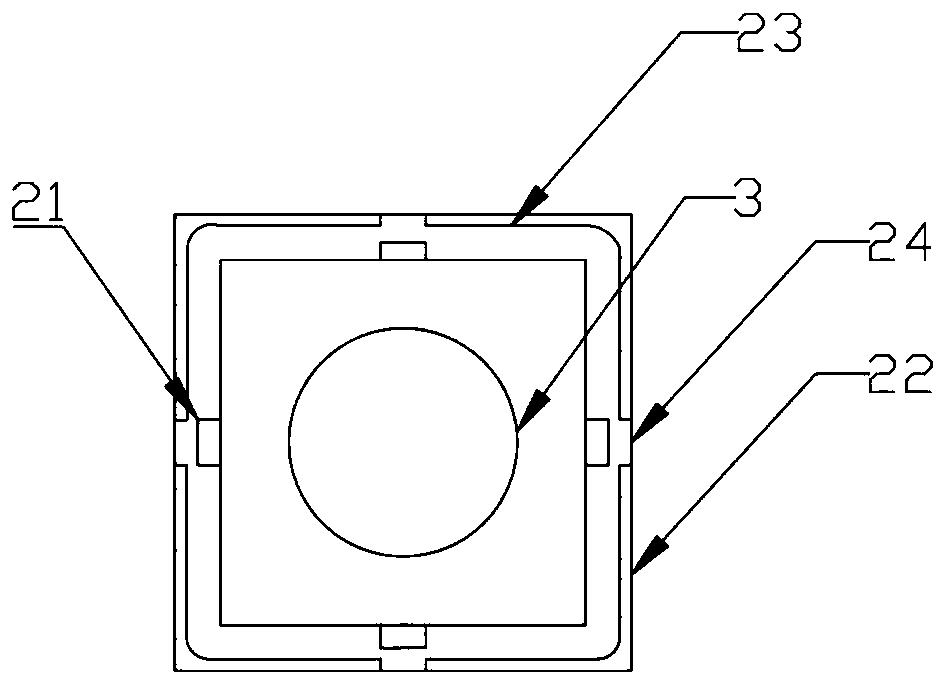
[0023] The secondary detection and early warning unit includes a liquid conductivity sensor, a pH value detection sensor, a secondary detection and early warning unit sensor group 21 of...


PUM


Abstract

The invention discloses a liquid hazardous chemical substance leakage bridge deck sensing detection early-warning device. A first-level detection early-warning unit is set beside a lane outside solidline beside each drainage opening of a bridge deck. Second-level detection early-warning units are set around each drainage opening in a semi-embedded mode. The first-level detection early-warning units and the second-level detection early-warning units are located on a flow channel of a bridge deck runoff. The first-level detection early-warning units are located at an upstream. Each first-leveldetection early-warning unit comprises a liquid dielectric constant detection sensor, a first storage module in which a rain and snow dielectric constant is pre-stored, a first CPU module, a first wireless communication module and a first protection shell. Each second-level detection early-warning unit comprises a liquid conductivity detection sensor, a PH value detection sensor, a liquid densitydetection sensor, a second storage module in which a detection index normal value is pre-stored, a second CPU module, a second wireless communication module and a second protection shell.

Description

technical field [0001] The invention relates to a bridge deck detection and early warning system capable of detecting leakage of liquid dangerous chemicals. Background technique [0002] As hazardous chemicals are transported more and more frequently across sea and river bridges, the types of hazardous chemicals are becoming more and more complicated. Once a transport leakage accident occurs, it will cause serious pollution to the water environment under the bridge, especially for cross-river and sea crossings. For bridges, it will seriously endanger ecological security. The emergency time for hazardous chemical leakage accidents is urgent, so the emergency measures are required to be simple, effective and widely applicable. Therefore, it is necessary to take measures for early detection and early warning of dangerous chemicals leaking from the bridge deck. [0003] Most of the currently designed bridge deck runoff detection systems for highway bridges are installed in the...

Claims


Application Information

Patent Timeline
Patent Type & Authority Applications(China)
IPC IPC(8): G01N27/07G08C17/02
CPCG01N27/07G08C17/02
Inventor 郭健陶行行
Owner ZHEJIANG UNIV OF TECH
Why Eureka
Try Eureka