Optical Frequency Domain Reflection Distributed Sensing Demodulation Method Based on Relative Phase Change
A technology of optical frequency domain reflection and relative phase, applied in the measurement of the change force of the optical properties of the material when it is stressed, and the use of optical devices, instruments, etc., can solve problems such as difficult and effective demodulation
- Summary
- Abstract
- Description
- Claims
- Application Information
AI Technical Summary
Problems solved by technology
Method used
Image

Examples
Embodiment 1
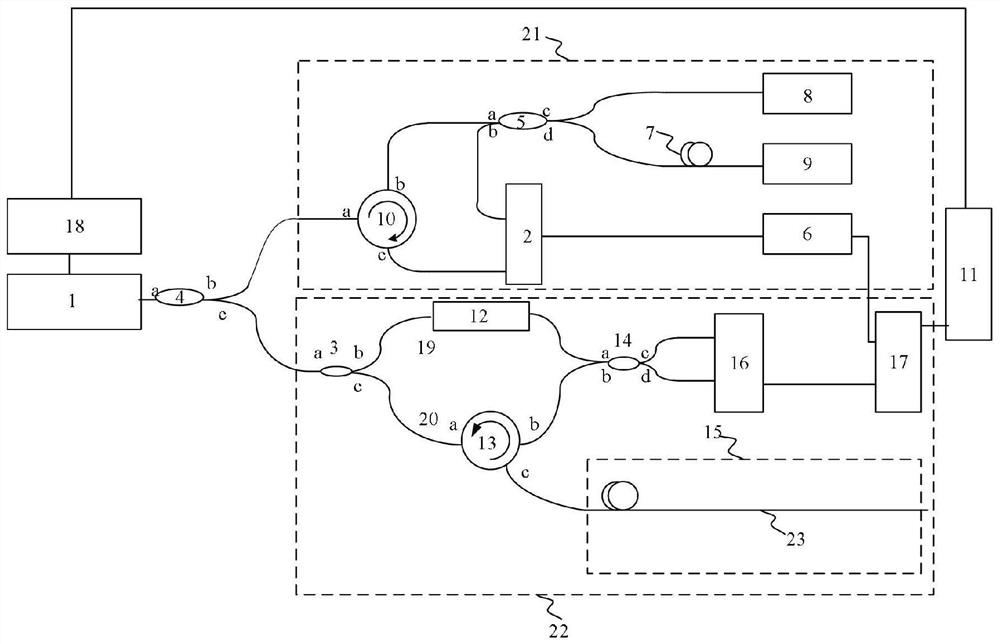
[0041] This example includes a distributed optical fiber sensing device based on an optical frequency domain reflectometry system, called an OFDR system. It includes: a tunable laser 1, a 95:5 optical beam splitter 4, a computer 11, a GPIB (General Purpose Interface Bus) control module 18, a clock trigger device 21 based on an auxiliary interferometer, and a main interferometer 22.
[0042] Wherein, the clock triggering device 21 based on the auxiliary interferometer includes: a first balance detector 2, a first 50:50 coupler 5, a clock shaping circuit module 6, a delay fiber 7, a first Faraday rotator 8, a second Faraday rotator Mirror 9 and first circulator 10. The clock trigger device 21 based on the auxiliary interferometer is used to realize equal optical frequency spacing sampling, and its purpose is to suppress the nonlinear scanning of the light source.
[0043] Wherein, the main interferometer 22 includes: an 80:20 beam splitter 3, a polarization controller 12, a sec...
Embodiment 2
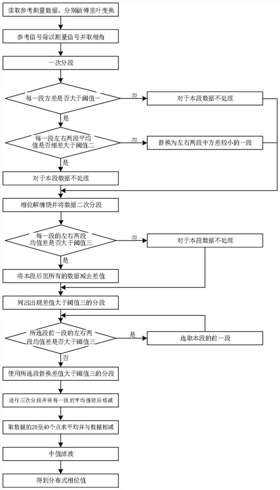
[0057] Embodiments of the invention provide a demodulation method for optical frequency domain reflective distributed sensing based on relative phase change, and strain sensing is taken as an example here. This sensing method is corresponding to the sensing system in embodiment 1, as figure 2 As shown, the steps of the sensing demodulation method are:
[0058] In the first step, OFDR is measured twice, one for reference data and one for measurement data, where the reference data is no strain change and the measurement data is strain change. In the main OFDR interferometer, the beat frequency interference signal is formed by the Rayleigh backscattering of the sensing fiber, which can be expressed as:
[0059]
[0060] where f 0 is the initial optical frequency, τ is the delay difference between the test light reflected at any position and the local oscillator reference light, R(τ) is the reflection coefficient, γ is the frequency sweep rate of the light source, Represen...
Embodiment 3
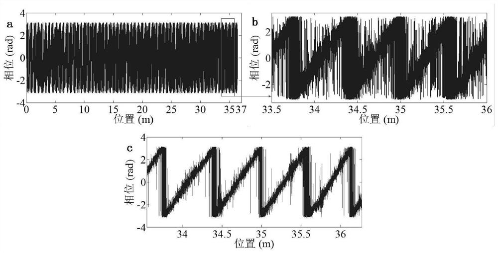
[0079] Below in conjunction with specific test, the sensing system and sensing method in embodiment 1-2 are verified for feasibility, see Image 6 with Figure 7 , see the description below:
[0080] The verification experiment of the embodiment of the present invention is to use the sensing fiber 23 as a continuous grating fiber. The long-distance fiber grating has a length of 34 m and consists of 3400 segments, each of which is 10 mm long. The grating length is 9 mm and the center wavelength is 1550 nm.
[0081] One end of the 40 cm at the end of the sensing fiber 23 is fixed, and the other end is glued to the nanometer displacement platform. The fiber is stretched from 0.1 to 1 micron, thus imparting 0.25 to 2.5 microstrain to the fiber. During the stretching process, data acquisition is carried out, and the corresponding micro-strain data are obtained. In the third segment, when 480 points are taken as the window, it means that the resolution of the whole system is 4.35cm...
PUM
| Property | Measurement | Unit |
|---|---|---|
| length | aaaaa | aaaaa |
| length | aaaaa | aaaaa |
| wavelength | aaaaa | aaaaa |
Abstract
Description
Claims
Application Information
 - Generate Ideas
- Intellectual Property
- Life Sciences
- Materials
- Tech Scout
- Unparalleled Data Quality
- Higher Quality Content
- 60% Fewer Hallucinations
Browse by: Latest US Patents, China's latest patents, Technical Efficacy Thesaurus, Application Domain, Technology Topic, Popular Technical Reports.
© 2025 PatSnap. All rights reserved.Legal|Privacy policy|Modern Slavery Act Transparency Statement|Sitemap|About US| Contact US: help@patsnap.com