
A cryogenic laser peening device and processing method

A laser peening and cryogenic technology, applied in manufacturing tools, heat treatment process control, heat treatment equipment, etc., can solve problems such as weakening the strengthening effect, generating a large number of bubbles, and affecting light transmittance

Active Publication Date: 2021-04-20
JIANGSU UNIV
View PDF4 Cites 0 Cited by
  • Summary
  • Abstract
  • Description
  • Claims
  • Application Information

AI Technical Summary

Problems solved by technology

However, the high light transmittance glass used is prone to water mist on the side in the air, which seriously reduces the light transmittance and weakens the strengthening effect
In addition, the volume of fixtures and workpieces at ultra-low temperatures will have a cold shrinkage effect, resulting in insufficient clamping force and easy pressure release, resulting in a decrease in shock wave pressure and further reducing the strengthening effect
For the constrained layer used in the cryogenic laser peening process, the invention patent of high light transmittance cryogenic laser shock head and laser shock system discloses the use of liquid nitrogen as the constrained layer in the cryogenic laser peening process, but at room temperature Due to the boiling of liquid nitrogen, a large number of bubbles will be generated inside the liquid nitrogen, which will reduce the strengthening effect
[0004] Since cryogenic laser peening requires laser peening treatment of the workpiece in an ultra-low temperature environment, however, in most cases the cryogenic temperature cannot reach the temperature of liquid nitrogen (-196°C), and the surface of the workpiece in the liquid nitrogen environment will produce liquid Nitrogen vapor and water mist seriously affect the light transmittance, thus greatly reducing the effect of cryogenic laser shot peening

Method used


Image

  • A cryogenic laser peening device and processing method
  • A cryogenic laser peening device and processing method
  • A cryogenic laser peening device and processing method

Examples


Embodiment Construction

[0031] The present invention will be further described below in conjunction with the accompanying drawings and specific embodiments, but the protection scope of the present invention is not limited thereto.

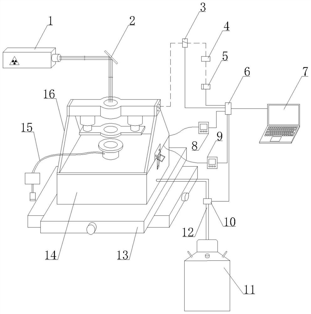
[0032] Such as figure 1 As shown, the cryogenic laser peening device of the present invention comprises laser 1, computer 7, workbench 13, low temperature control device 14, drying device 15, PLC6 and pressure control device 16, and described low temperature control device 14 is fixed on the working On the platform 13, the worktable 13 can move in a plane; the pressure control device 16 cooperates with the low temperature control device 14 and is fixed through a lock connection.

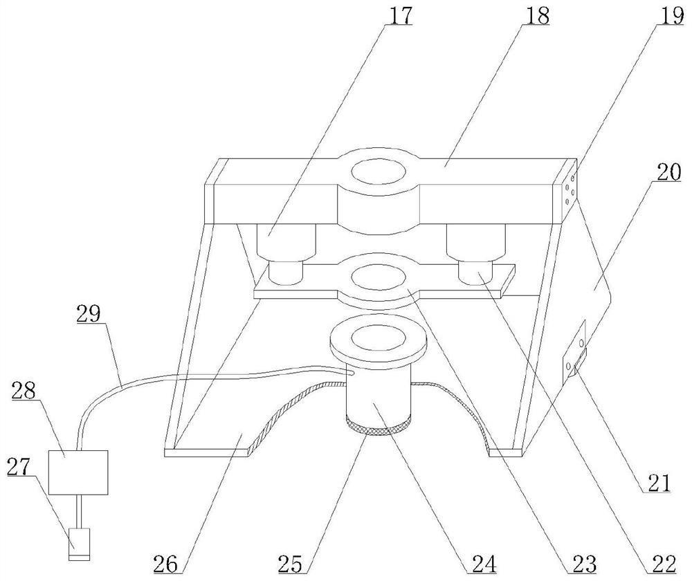
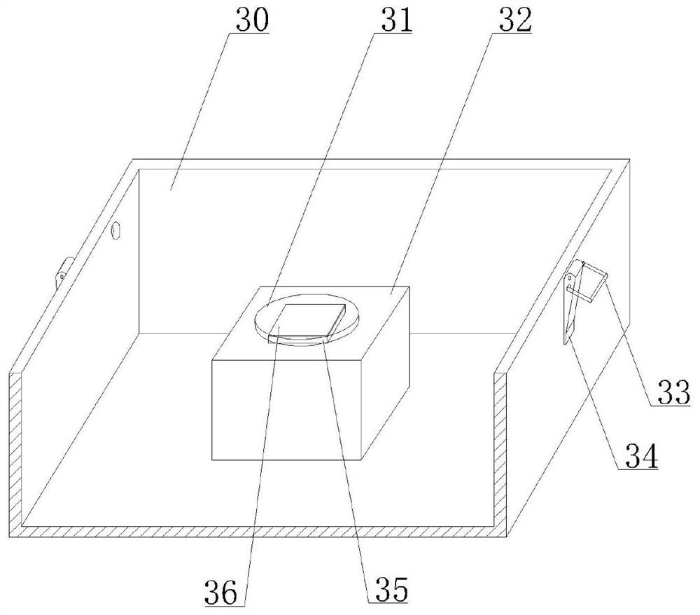
[0033] Such as figure 2 and image 3 As shown, the low temperature control device 14 includes a cryogenic box 30, a flow control valve 10, a liquid nitrogen tank 11, a liquid nitrogen delivery pipe 12 and an ultra-low temperature sensor 9, and the cryogenic box 30 is fixed on the workbench 13...


PUM

PropertyMeasurementUnit
diameteraaaaaaaaaa

Abstract

The invention provides a cryogenic laser peening device and processing method, comprising a laser emission system, a low temperature control device, a drying device, a pressure control device and a control system; the laser emission system is used to generate laser beams; the low temperature control The device includes a cryogenic box and a liquid nitrogen delivery system, the liquid nitrogen delivery system is used to deliver liquid nitrogen into the cryogenic box; a workpiece is installed in the cryogenic box, a hollow gland is placed on the workpiece, and the pressure The control device is used to apply pressure on the gland, and the laser beam passes through the gland to irradiate the surface of the workpiece; the drying device is used to dry the air inside the gland; the control system is used to control the delivery of liquid nitrogen system, laser emission system and pressure control device. The invention realizes that the cryogenic temperature can reach the liquid nitrogen temperature, the cryogenic temperature is controllable, the light transmittance is improved and the confinement effect is better, and the cryogenic laser shot peening strengthening effect is improved.

Description

technical field [0001] The invention relates to the field of laser shock processing, in particular to a cryogenic laser peening device and a processing method. Background technique [0002] As a new surface strengthening process, laser peening has the advantages of obvious grain refinement and influence on layer depth, which can effectively improve the fatigue resistance, wear resistance and corrosion resistance of metal materials, so it is widely used in aerospace, automobile and Ships and many other fields. However, the current laser peening technology is generally carried out at room temperature. During the peening process, the dynamic recovery of grains and the annihilation of some dislocations will occur. The strength of the material is greatly improved but the improvement of plasticity is not particularly obvious, so it cannot reach the level of aerospace alloys. Requirements. Cryogenic treatment, also known as ultra-low temperature treatment, mainly refers to the lo...

Claims


Application Information

Patent Timeline
Patent Type & Authority Patents(China)
IPC IPC(8): C21D10/00C21D11/00
CPCC21D10/005C21D11/00
Inventor 周建忠田绪亮李京孟宪凯孙昀杰黄宇黄舒
Owner JIANGSU UNIV
Learn More