
Electric gain frequency-selecting cavity-based frequency tunable optoelectronic oscillator system

A photoelectric oscillator and frequency selection technology, applied in the direction of solid-state lasers, etc., can solve the problem that tunable microwave source technology cannot meet low phase noise and high side mode suppression ratio at the same time, achieve good side mode suppression effect, suppress side mode , The system structure is simple and easy to achieve

Active Publication Date: 2019-12-13
TIANJIN UNIV
View PDF5 Cites 4 Cited by
  • Summary
  • Abstract
  • Description
  • Claims
  • Application Information

AI Technical Summary

Problems solved by technology

[0005] In view of the above prior art, the present invention proposes a frequency tunable optoelectronic oscillator system based on an electrical gain frequency selective cavity, which solves the problem that the existing tunable microwave source technology cannot simultaneously satisfy low phase noise and high side mode suppression ratio, The system structure of the present invention is simple and easy to realize, and fine tuning can be realized by controlling the electric phase shifter and the optical delay line, while not only retaining the advantages of OEO low phase noise, but also effectively suppressing side modes, and having high system stability, The invention can be used as a stable signal generator for generating high-quality tunable output signals

Method used


Image

  • Electric gain frequency-selecting cavity-based frequency tunable optoelectronic oscillator system
  • Electric gain frequency-selecting cavity-based frequency tunable optoelectronic oscillator system
  • Electric gain frequency-selecting cavity-based frequency tunable optoelectronic oscillator system

Examples


Embodiment Construction

[0014] The present invention will be further described below in conjunction with the accompanying drawings and specific embodiments, but the following embodiments in no way limit the present invention.

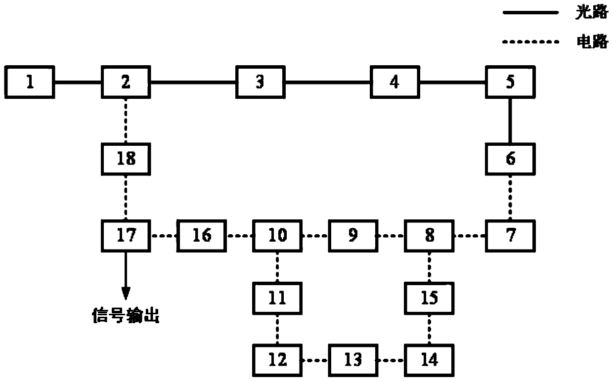
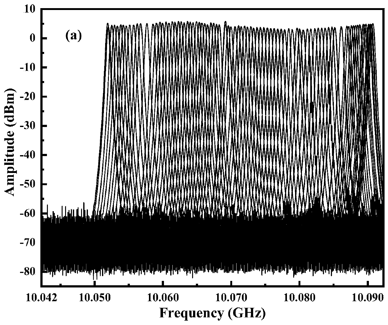
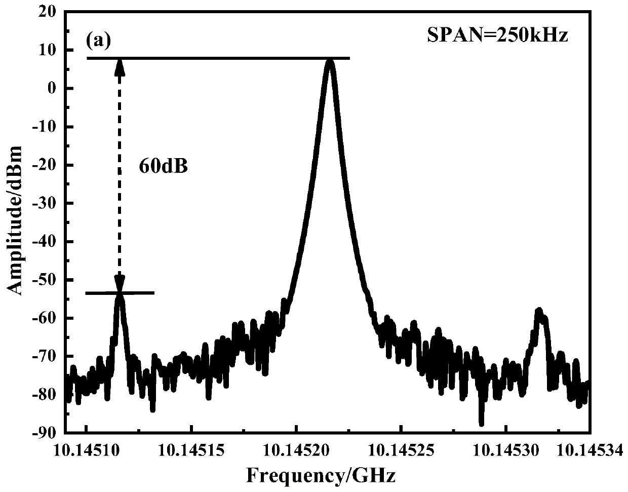
[0015] Such as figure 1 As shown, a frequency tunable optoelectronic oscillator system based on an electrical gain frequency selective cavity proposed by the present invention is based on the principle of electrical injection locking, and the OEO free oscillation signal and the electrical gain frequency selection are made by adjusting the optical delay line and the phase shifter. The cavity output signal satisfies the electric injection locking condition, the output signal frequency is changed, and the output frequency can be tuned.

[0016] The system includes the following optical devices and electronic devices: laser 1, intensity modulator 2, single-mode fiber 3, adjustable optical attenuator 4, optical delay line 5, photodetector 6, bandpass filter 9, five Microwave ampli...


PUM


Abstract

The invention discloses an electric gain frequency-selecting cavity-based frequency tunable optoelectronic oscillator system. A single-loop OEO (optoelectronic oscillator) is combined with an electricgain frequency-selecting cavity formed by a microwave filter, electric attenuators, an electric phase shifter and the like; the signals of the electric gain frequency-selecting cavity can be locked to the electric injection of the free oscillation signals of the OEO, so that the output of system signals can be realized; the frequency of the output signals is determined by the electric gain frequency-selecting cavity for locking the mode of the OEO; the bias voltage of the electric phase shifter is adjusted, so that the frequency of microwave signals outputted by the electric frequency-selecting cavity can be changed; an optical delay line is adjusted, so that the oscillation starting mode of the single-loop OEO can be changed; the electric phase shifter and the optical delay line can be adjusted, so that the frequency tuning of the output signals can be adjusted; and the electric attenuators can be adjusted, so that the loop cavity gain of the OEO can be matched with the electric gainfrequency-selecting cavity, so that a side mode can be effectively restrained. The system is simple in structure. According to the system, the advantage of the low-phase noise of the single-loop OEOis reserved, the side mode can be effectively suppressed, and a new implementation method is provided for the frequency tunable OEO.

Description

technical field [0001] The invention relates to a frequency tunable photoelectric oscillator system based on an electric gain frequency selective cavity. Background technique [0002] High-performance microwave sources are the basis of all microwave applications, and their phase noise, spectral purity, and stability directly affect the performance of electronic equipment in aerospace, instrumentation, radar, and many other fields. With the improvement of application requirements, the noise performance of traditional microwave sources is approaching the limit. The optoelectronic oscillator (OEO) is a new type of microwave signal generator with high spectral purity, and its Q value is as high as 10 10 It is an ideal high-performance microwave oscillator that can generate microwave signals with a frequency up to hundreds of GHz and a phase noise lower than -160dBc / Hz@10kHz. [0003] In various applications such as frequency division multiplexing and radar detection required f...

Claims


Application Information

Patent Timeline
IPC IPC(8): H01S1/02
CPCH01S1/02
Inventor 王菊方杰于晋龙马闯
Owner TIANJIN UNIV
Learn More