
Flexure Mounted Moving Mirror to Reduce Vibration Noise

a moving mirror and vibration noise technology, applied in the field of optical scientific instruments, can solve the problems of only operating systems, only correcting velocity errors, and expensive stiff precision mechanical interferometer systems, and achieve the effect of improving velocity control, stable and low noise spectral data

Active Publication Date: 2012-05-17
THERMO ELECTRONICS SCI INSTR LLC
View PDF14 Cites 20 Cited by
  • Summary
  • Abstract
  • Description
  • Claims
  • Application Information

AI Technical Summary

Benefits of technology

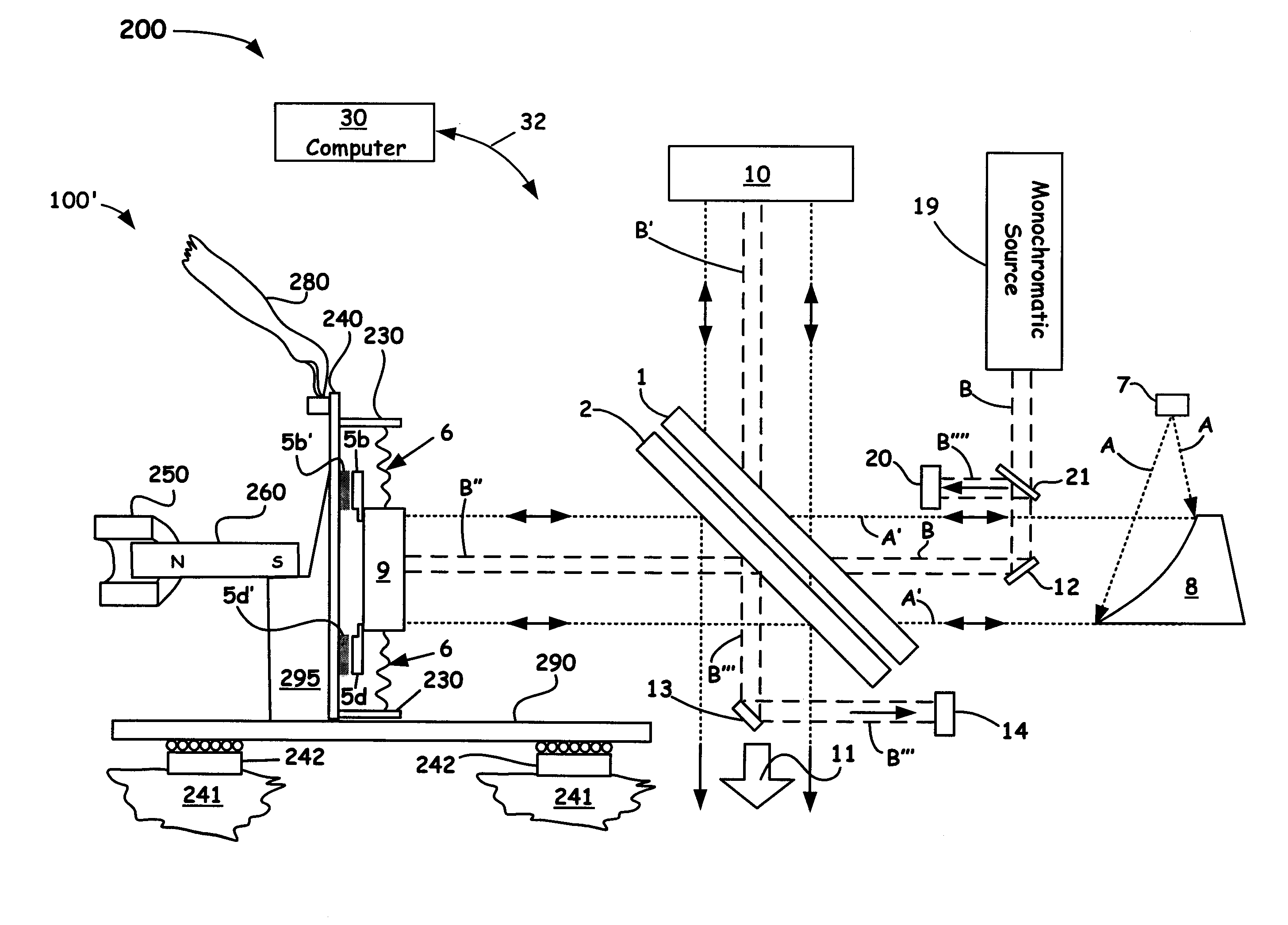
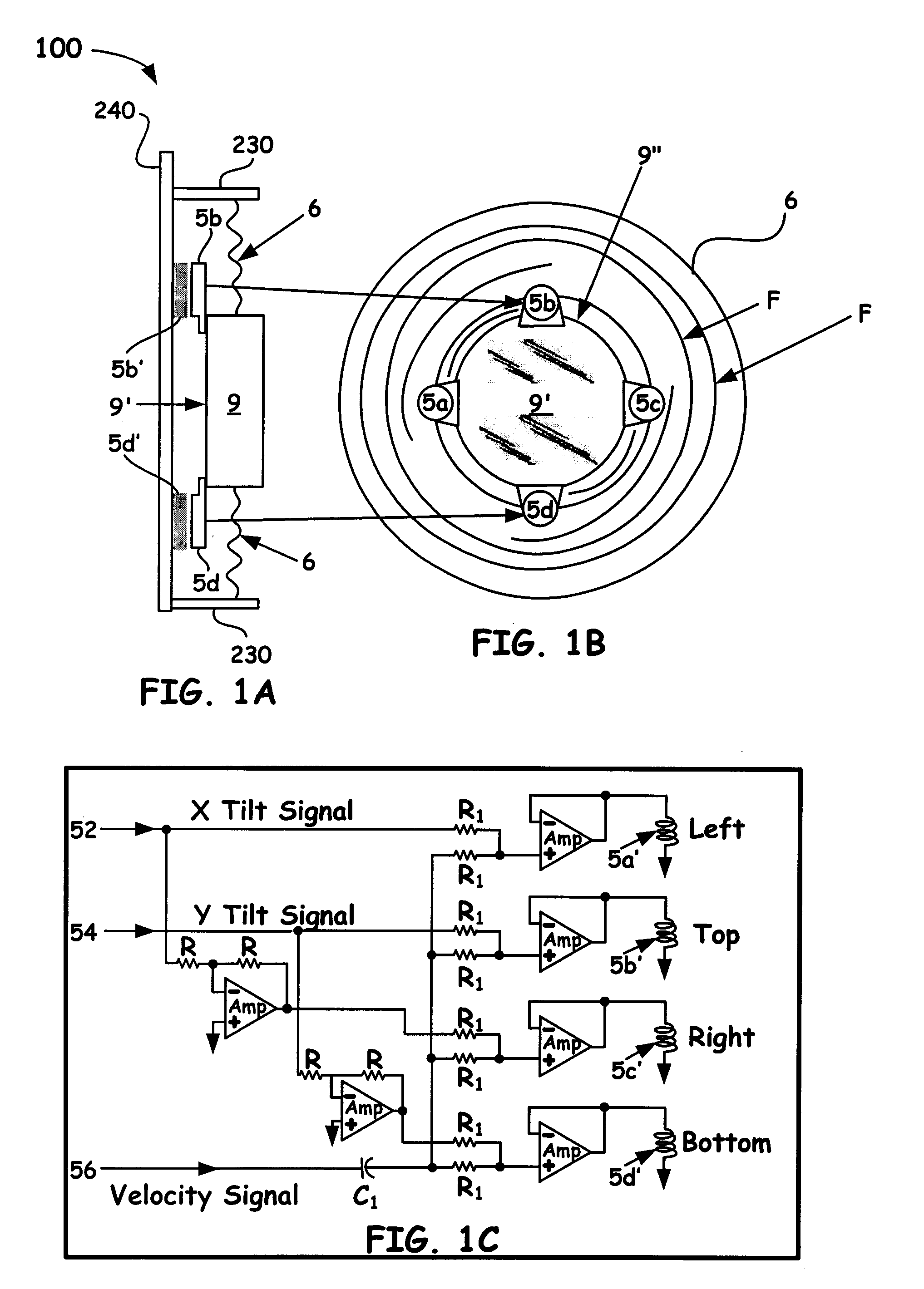
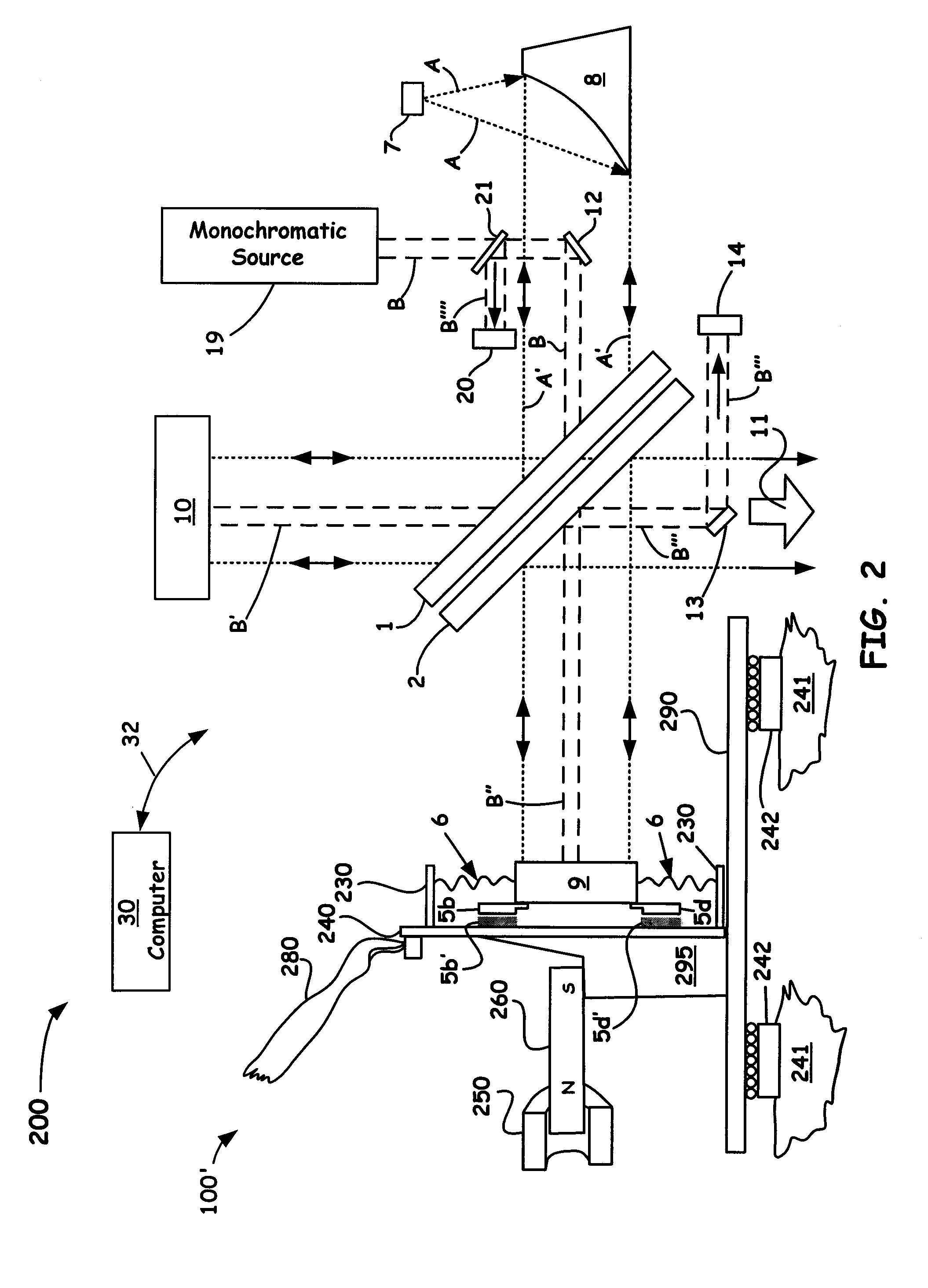
[0010]The present invention is directed to a novel hybrid moving mirror assembly that includes: a reflector; a resilient member coupled about the periphery of the reflector and further coupled to a support structure; wherein the resilient member minimizes induced external stresses directed through the support structure and wherein the resilient member is configured to provide a retarding force when flexed. The assembly also includes a first plurality of movement means coupled to a predetermined surface of the reflector; a second plurality of movement means configured to couple matched and / or mismatched predetermined forces with the first movement means, wherein the matched and / or mismatched predetermined forces enables short stroke linear movement and / or X, Y tilting movements of the reflector; and a linear movement means coupled to the support structure to provide long stroke velocity and position control of the resiliently mounted reflector.
[0012]Accordingly, the present invention provides for a beneficial hybrid combination of a long stroke bearing system and a coupled short stroke resilient bearing mirror arrangement within an interferometer instrument. Such an arrangement enables correction of the errors at the mirror itself while also solving the problem of isolating vibration and noise caused by the imperfections in the bearing surfaces used in many conventional interferometers. Using such a coupled flexure mounting of the present invention, in addition to the above benefits, also enhances velocity control because the resultant low mass of the moving mirror assembly enables the systems disclosed herein to respond faster than conventional mirror velocity controlled interferometer instruments so as to provide for more stable and lower noise spectral data.

Problems solved by technology

Because of the delicate nature of such instruments, conventional systems are often configured to be precisely aligned with mechanical adjustments that must stay correctly adjusted even if the system is shipped around the world.
This has resulted in expensive stiff precision mechanical interferometer systems that sometimes need adjustments in the field after shipping shocks has shifted the alignment of the critical flat optical surfaces.
Such systems can only operate if the interferometer is scanning under the control of a laser based velocity control servo that all typical scanning interferometers use.
However, it is to be noted that while all practical interferometers use one or more laser based velocity measuring systems to enable a servo control system to control the velocity of the moving mirror, such servos can only correct velocity errors after a small time delay (caused by the velocity measurement process and the delay in generating correcting forces).
However velocity errors that occur at a rapidly changing rate due to induced noise cannot be corrected completely leaving a remaining velocity error that negatively affects the spectra data collected.

Method used


Image

  • Flexure Mounted Moving Mirror to Reduce Vibration Noise
  • Flexure Mounted Moving Mirror to Reduce Vibration Noise
  • Flexure Mounted Moving Mirror to Reduce Vibration Noise

Examples


Embodiment Construction

[0018]In the description of the invention herein, it is understood that a word appearing in the singular encompasses its plural counterpart, and a word appearing in the plural encompasses its singular counterpart, unless implicitly or explicitly understood or stated otherwise. Furthermore, it is understood that for any given component or embodiment described herein, any of the possible candidates or alternatives listed for that component may generally be used individually or in combination with one another, unless implicitly or explicitly understood or stated otherwise. Moreover, it is to be appreciated that the figures, as shown herein, are not necessarily drawn to scale, wherein some of the elements may be drawn merely for clarity of the invention. Also, reference numerals may be repeated among the various figures to show corresponding or analogous elements. Additionally, it will be understood that any list of such candidates or alternatives is merely illustrative, not limiting, u...


PUM


Abstract

A novel means of provided a hybrid flexure mounted moving mirror component in an interferometer is introduced herein. In particular, a linear bearing in combination with a novel flexure mounting having novel tilt and velocity control of the moving optical component is provided. Such an arrangement enables correction of the errors at the mirror itself while also solving the problem of isolating vibration and noise caused by the imperfections in the bearing surfaces used in many conventional interferometers. Using such a coupled flexure mounting of the present invention, in addition to the above benefits, also enhances velocity control because the resultant low mass of the moving mirror assembly enables the systems disclosed herein to respond faster than conventional mirror velocity controlled interferometer instruments and with a lower velocity error so as to provide a more stable and lower noise spectra from the analytical instrument.

Description

RELATED APPLICATIONS[0001]This application is a Continuation-in-Part of U.S. patent application Ser. No. 12 / 944,512 entitled: “INTERFEROMETER VELOCITY CONTROL OF BEAMSPLITTER AND MOVING MIRRORS,” filed Nov. 11, 2010, and of U.S. patent application Ser. No. 12 / 944,428, entitled: “DUAL INPUT INTERFEROMETER BEAMSPLITTER TILT CONTROL SYSTEM AND FLEXURE MOUNTING,” also filed on Nov. 11, 2010, both of which are incorporated by reference in its entirety.BACKGROUND OF THE INVENTION[0002]1. Field of the Invention[0003]The present invention relates to the field of optical scientific instrumentation. More specifically, the present invention relates to a novel flexure coupled moving mirror utilized in a Fourier-Transform infrared (FTIR) interferometer.[0004]2. Discussion of the Related Art[0005]An optical interferometer used in a scientific analytical instrument relies on the interference of superimposed optical beams as part of the interrogation means. When configured as a Michelson Fourier-Tr...

Claims


Application Information

Patent Timeline
Patent Type & Authority Applications(United States)
IPC IPC(8): G01J3/45G02B26/00
CPCG01J3/4535G02B26/101G01J9/02
Inventor COFFIN, JOHN MAGIE
Owner THERMO ELECTRONICS SCI INSTR LLC
Learn More