A wireless power transfer adaptive frequency tracking method and system based on switching control
A technology of wireless power transmission and frequency tracking, applied in power management, charging stations, collectors, etc., can solve problems such as poor stability and safety of converters, reduce production and maintenance costs, reduce product failure rates, and improve The effect of system efficiency
- Summary
- Abstract
- Description
- Claims
- Application Information
AI Technical Summary
Problems solved by technology
Method used
Image
Examples
Embodiment 1
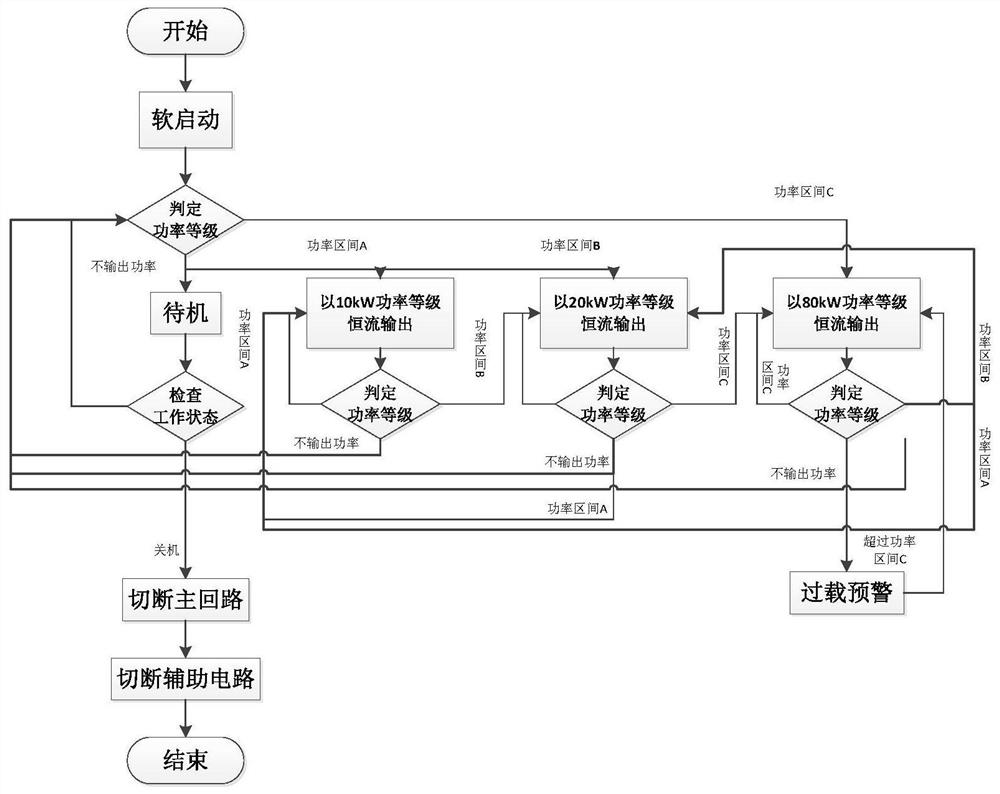
[0035] An adaptive frequency tracking method for wireless power transfer based on handoff control, such as image 3 as shown,
[0036] The method comprises the steps of:
[0037]Step 1: Controlling the soft start of the wireless power transmission inverter power supply system, and preset the control initial value;
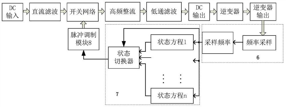
[0038] Step 2: The output frequency sampling mechanism 6 performs time domain and frequency domain data preprocessing on the frequency characteristic parameters of the output electric energy of the inverter 2 and the electrical parameters of other auxiliary state switching units 7, such as multi-point Data processing and feature extraction algorithms such as averaging, digital filtering, and discrete Fourier transform.
[0039] Step 3: The state switching unit 7 effectively identifies the output load characteristics by extracting the electrical parameter characteristics described in step 2 and matching with the pre-stored state equation, and divides the power lev...
Embodiment 2
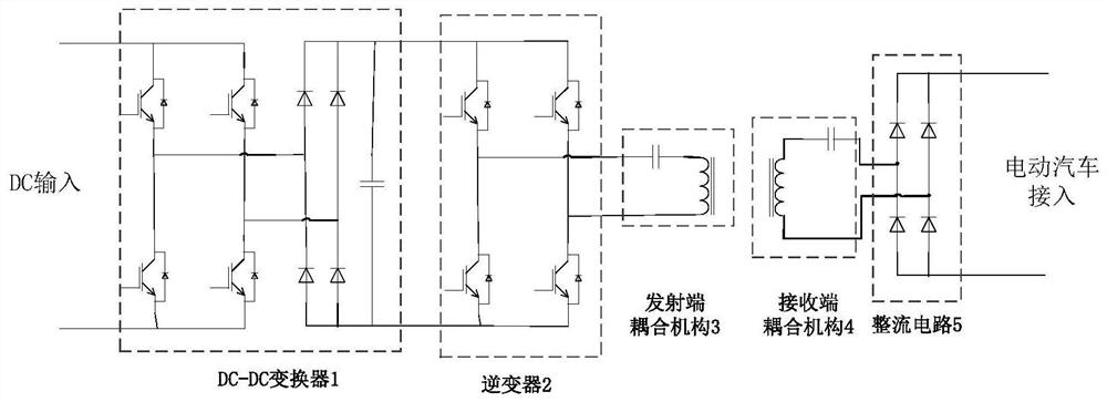
[0043] A wireless power transfer adaptive frequency tracking system implementing the tracking method described in Embodiment 1, such as figure 1 with figure 2 As shown, the system includes: the system includes a DC-DC converter 1, an inverter 2, a transmitting end coupling mechanism 3, a receiving end coupling mechanism 4, a rectifier circuit 5, an output frequency sampling mechanism 6, and a state switching unit 7 and a pulse modulation module 8; the power signal input end of the DC-DC converter 1 is connected to the DC power input; the power signal output end of the DC-DC converter 1 is connected to the power signal input end of the inverter 2 Connected; the coupling end of the transmitting end coupling mechanism 3 is connected to the coupling end of the receiving end coupling mechanism 4 through inductive coupling; the power signal output end of the receiving end coupling mechanism 4 is connected to the power signal input end of the rectification circuit 5 connected; the ...
PUM
 Abstract
Description
Claims
Application Information
 - R&D
- Intellectual Property
- Life Sciences
- Materials
- Tech Scout
- Unparalleled Data Quality
- Higher Quality Content
- 60% Fewer Hallucinations
Browse by: Latest US Patents, China's latest patents, Technical Efficacy Thesaurus, Application Domain, Technology Topic, Popular Technical Reports.
© 2025 PatSnap. All rights reserved.Legal|Privacy policy|Modern Slavery Act Transparency Statement|Sitemap|About US| Contact US: help@patsnap.com


