Structural color material and preparation method thereof
A technology for structural color and thin film materials, applied in the field of nano optics, can solve the problems of complex preparation methods and poor controllability of structural color materials, and achieve the effects of simple operation, increased product practicability, and strong controllability
- Summary
- Abstract
- Description
- Claims
- Application Information
AI Technical Summary
Problems solved by technology
Method used
Image

Examples
Embodiment 1
[0057] This embodiment prepares the structural color material according to the following method:
[0058] (1) A tin metal layer is plated on a silica glass substrate by magnetron sputtering, and then a silicon dioxide protective layer is plated on the tin metal layer by magnetron sputtering to obtain a thin film material. The coating parameters are argon flow rate of 25SCCM, coating power of 50W and 250W, coating time of 270s and 4650s respectively, and the thickness of the metal tin layer is 100nm; the thickness of the silicon dioxide protective layer is 20nm.
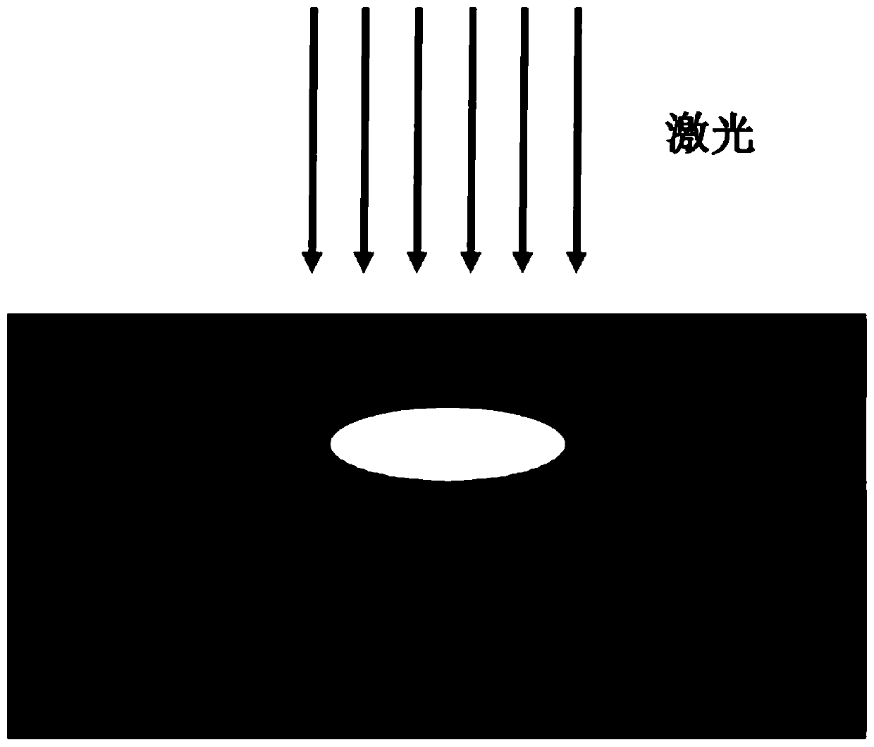
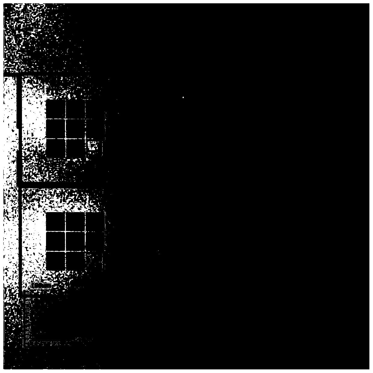
[0059] (2) Determine the color and graphics to be written (in this embodiment, the monochromatic nine-grid pattern of various colors is formed), the laser direct writing system is set, and the laser direct writing system is used according to the set color and graphics under the air atmosphere. The laser of the writing system is irradiated from above the protective layer, and the film material described in step (1) is ...
Embodiment 2
[0065] The only difference between this embodiment and embodiment 1 is that in the step (2) of this embodiment, a specific butterfly pattern is written, rather than the nine-square grid formed by a single color in embodiment 1. In this embodiment, in addition to setting the laser direct writing system according to the butterfly pattern, step (1) the preparation method of the thin film material, step (2) the range of laser power and the laser direct writing processing time of each processing site are all the same as Example 1 is the same.
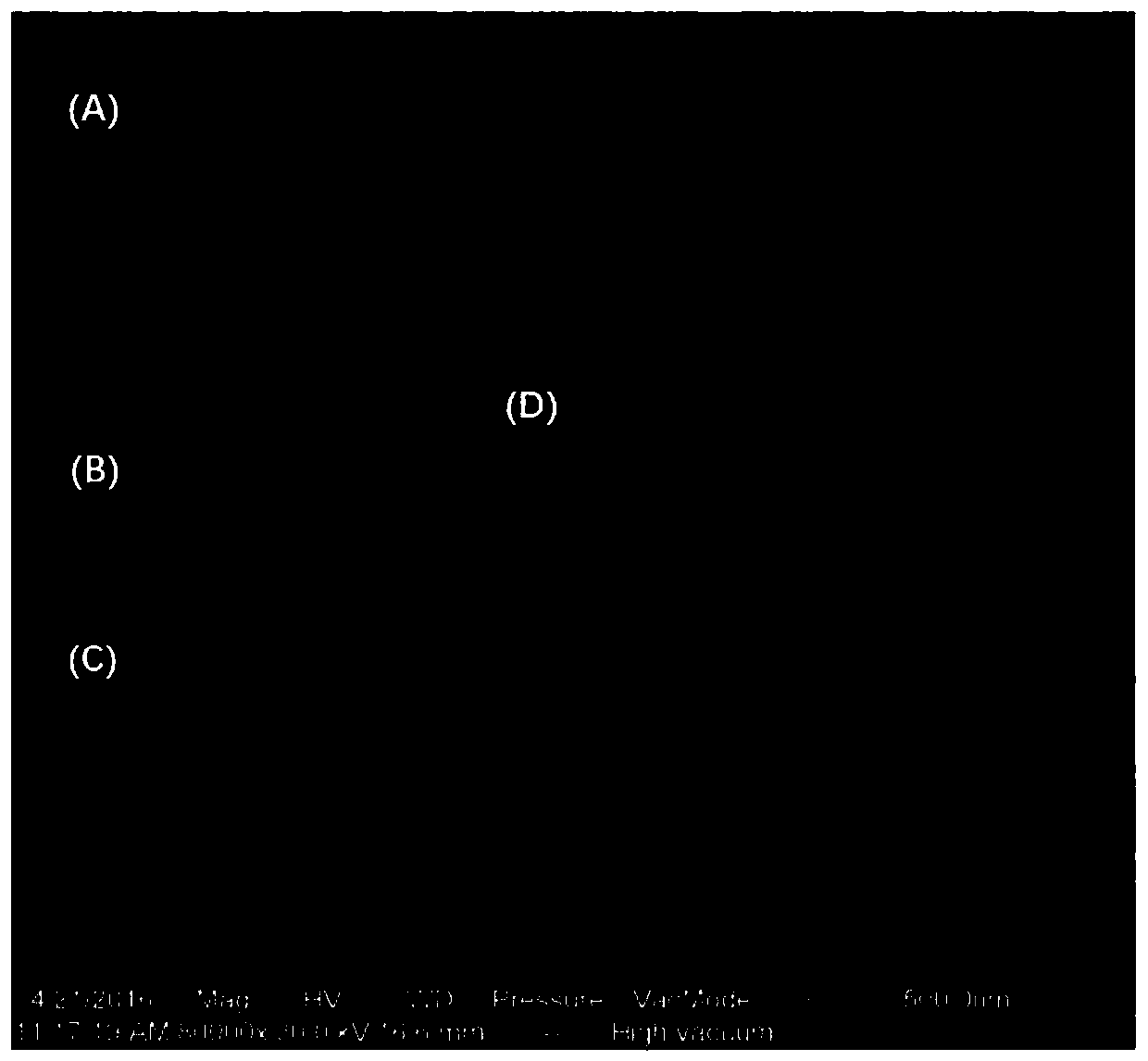
[0066] The structural color material prepared in this example consists of a silica glass substrate, a tin metal layer (thickness 100nm) on the silica glass substrate, and a silicon dioxide protective layer (thickness 20nm) on the tin metal layer, The tin metal layer contains an array formed by periodic and ordered arrangement of nano cavities. The nano-cavities include biconvex disc-shaped cavities and bi-convex disc-like cavities, the diam...
Embodiment 3
[0069] This embodiment prepares the structural color material according to the following method:
[0070] (1) On the silica glass substrate, use the molecular beam epitaxy method magnetron sputtering method to coat the tin metal layer, then use the plasma enhanced chemical vapor deposition (PECVD) method magnetron sputtering method on the tin metal layer Plating a protective layer of silicon dioxide to obtain a thin film material. The coating parameters are argon flow rate of 25SCCM, coating power of 50W and 250W, and coating time of 270s and 4650s respectively. The thickness of the metal tin layer is 100nm; the thickness of the silicon dioxide protective layer is 8520nm.
[0071] (2) Determine the color and graphics (in this embodiment, red monochrome graphics) to write, set the laser direct writing system, and use the laser of the laser direct writing system under the air atmosphere to protect Irradiate above the layer, carry out laser direct writing processing to the thin ...
PUM
| Property | Measurement | Unit |
|---|---|---|
| Diameter | aaaaa | aaaaa |
| Height | aaaaa | aaaaa |
| Thickness | aaaaa | aaaaa |
Abstract
Description
Claims
Application Information
 - R&D
- Intellectual Property
- Life Sciences
- Materials
- Tech Scout
- Unparalleled Data Quality
- Higher Quality Content
- 60% Fewer Hallucinations
Browse by: Latest US Patents, China's latest patents, Technical Efficacy Thesaurus, Application Domain, Technology Topic, Popular Technical Reports.
© 2025 PatSnap. All rights reserved.Legal|Privacy policy|Modern Slavery Act Transparency Statement|Sitemap|About US| Contact US: help@patsnap.com