
Semiconductor structure, preparation method of transistor structure and semiconductor processing device

A technology for processing equipment and semiconductors, applied in the fields of semiconductor/solid-state device manufacturing, transistors, semiconductor devices, etc., can solve the problems of increasing the power consumption of electronic devices and the impact of device performance, reducing junction leakage current, reducing power consumption, and reducing EOR The effect of defects

Pending Publication Date: 2019-12-03
CHANGXIN MEMORY TECH INC
View PDF0 Cites 1 Cited by
  • Summary
  • Abstract
  • Description
  • Claims
  • Application Information

AI Technical Summary

Problems solved by technology

The EOR (End of Range) defect formed after ion implantation and annealing in semiconductor manufacturing will lead to junction leakage (Junction leakage). In the prior art, such as in the preparation of source and drain regions, the EOR defect layer is relatively thick, resulting Leakage current (10 -5 ~10 -8 A / CM 2 ), thus increasing the power consumption of electronic devices
[0004] Therefore, how to provide a method for preparing a semiconductor structure, a transistor structure, and a semiconductor device is necessary to solve the problem that EOR defects have a serious impact on device performance in the prior art

Method used


Image

  • Semiconductor structure, preparation method of transistor structure and semiconductor processing device
  • Semiconductor structure, preparation method of transistor structure and semiconductor processing device
  • Semiconductor structure, preparation method of transistor structure and semiconductor processing device

Examples


Embodiment Construction

[0057] Embodiments of the present invention are described below through specific examples, and those skilled in the art can easily understand other advantages and effects of the present invention from the content disclosed in this specification. The present invention can also be implemented or applied through other different specific implementation modes, and various modifications or changes can be made to the details in this specification based on different viewpoints and applications without departing from the spirit of the present invention.

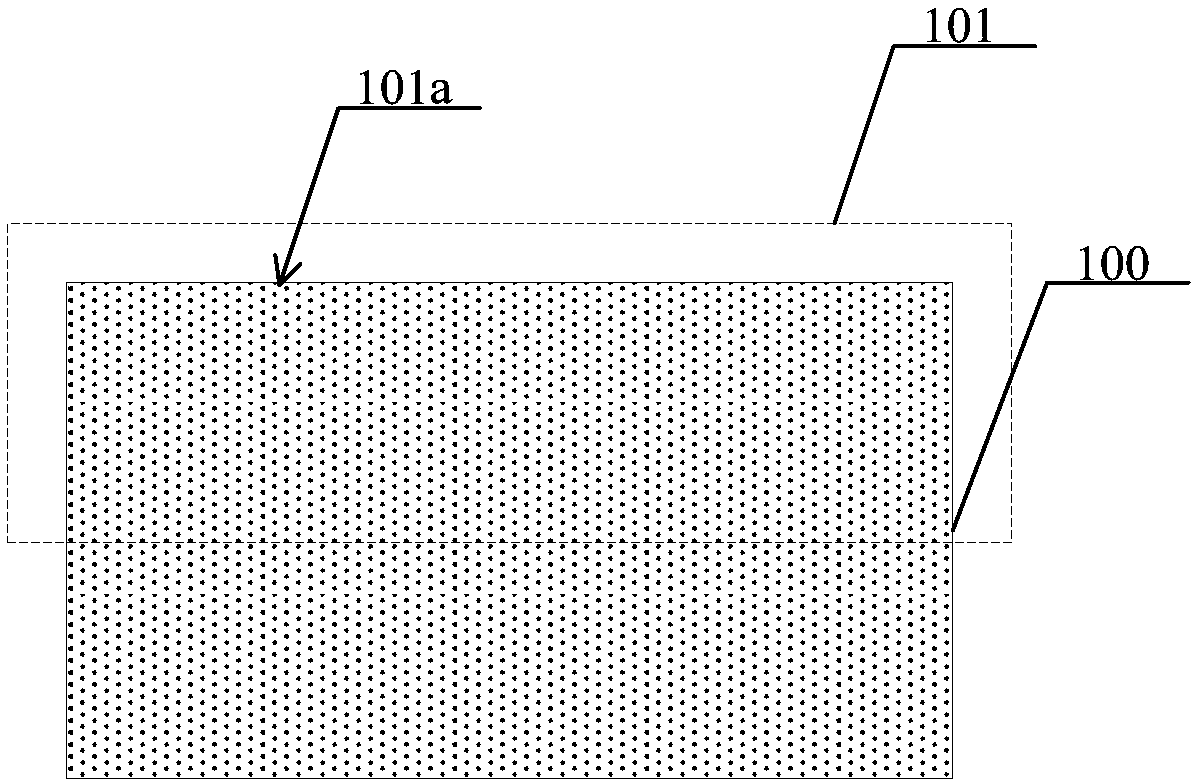
[0058] see Figure 1 to Figure 6 . It should be noted that the diagrams provided in this embodiment are only schematically illustrating the basic concept of the present invention, although only the components related to the present invention are shown in the diagrams rather than the number, shape and Dimensional drawing, the shape, quantity and proportion of each component can be changed arbitrarily during actual implementation, and ...


PUM


Abstract

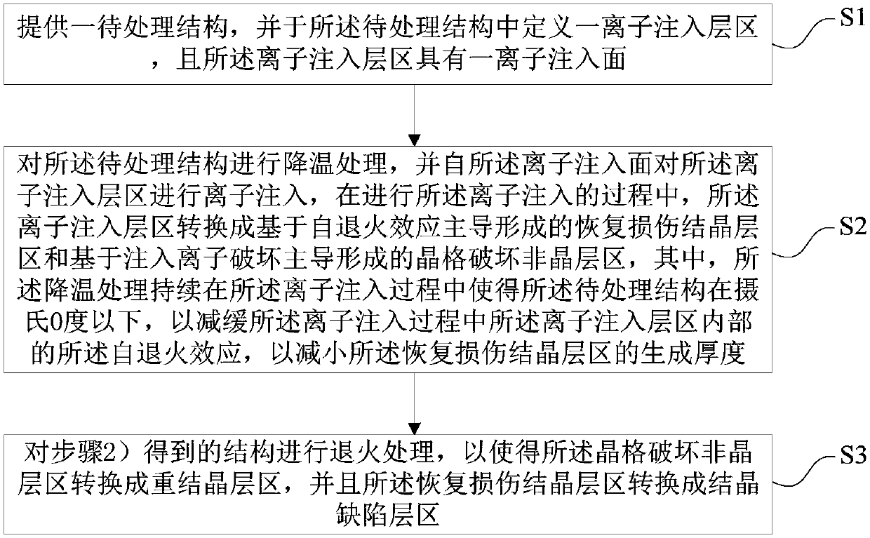
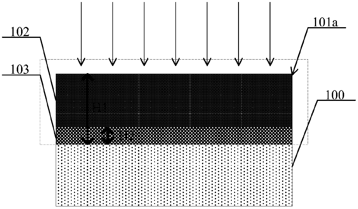
The invention discloses a semiconductor structure based on low-temperature ion implantation, transistor preparation and a semiconductor processing device. The method comprises the steps of: providinga to-be-processed structure, and defining an ion implantation layer region with an ion implantation surface; cooling the to-be-processed structure, performing ion implantation from the ion implantation surface, wherein in the ion implantation process, an ion implantation layer area is converted into a recovery damage crystallization layer area and a lattice damage amorphous layer area, the self-annealing effect in the ion implantation layer area is relieved through cooling treatment, and the size of the recovery damage crystallization layer area is reduced; and performing annealing treatment,converting the lattice damage amorphous layer area into a recrystallization layer area, and converting the recovery damage crystallization layer area into a crystallization defect layer area. The to-be-processed structure is cooled in the ion implantation process, ion implantation is carried out under the low-temperature condition, and the self-annealing effect in the ion implantation process is relieved, so that the EOR defect after annealing is reduced, the junction leakage current is reduced, and the power consumption of an electronic device is reduced.

Description

technical field [0001] The invention belongs to the technical field of semiconductor device structure preparation, and in particular relates to a method for preparing a semiconductor structure based on low-temperature ion implantation, a method for preparing a transistor structure, and semiconductor processing equipment. Background technique [0002] Dynamic Random Access Memory (DRAM for short) is a semiconductor storage device commonly used in computers, and is composed of many repeated storage units. Each memory cell usually includes a capacitor and a transistor; the gate of the transistor is connected to the word line, the drain is connected to the bit line, and the source is connected to the capacitor; the voltage signal on the word line can control the opening or closing of the transistor, and then through the bit line Read the data information stored in the capacitor, or write the data information into the capacitor through the bit line for storage. At present, in th...

Claims


Application Information

Patent Timeline
Patent Type & Authority Applications(China)
IPC IPC(8): H01L27/108H01L29/06H01L21/265H10B12/00
CPCH01L29/0603H01L29/0684H01L21/26593H10B12/00H10B12/01
Inventor 刘铁
Owner CHANGXIN MEMORY TECH INC
Learn More