
Method for enhancing creep resistance of ceramic mold core through customization

A technology for ceramic casting and creep resistance, which is used in ceramic molding machines, casting molds, cores, etc., can solve the problems of affecting the surface roughness of the inner cavity of the casting mold and not using it, and achieves strong shape retention ability and improved resistance. Deformation ability, strength-enhancing effect

Inactive Publication Date: 2019-11-19
XI AN JIAOTONG UNIV
View PDF3 Cites 1 Cited by
  • Summary
  • Abstract
  • Description
  • Claims
  • Application Information

AI Technical Summary

Problems solved by technology

[0003] The traditional method is to increase the strength of the core by adding carbon fiber to the ceramic slurry, but this only improves the local strength and will affect the surface roughness of the inner cavity of the mold
Also, conventional methods do not employ specific protocols for specific ceramic materials and mold shapes

Method used


Image

  • Method for enhancing creep resistance of ceramic mold core through customization
  • Method for enhancing creep resistance of ceramic mold core through customization
  • Method for enhancing creep resistance of ceramic mold core through customization

Examples


Embodiment 1

[0048] For the up and down straight-through core, the method of customizing and enhancing the creep resistance of the monolithic ceramic casting core includes the following steps:

[0049] 1) SL model design and preparation

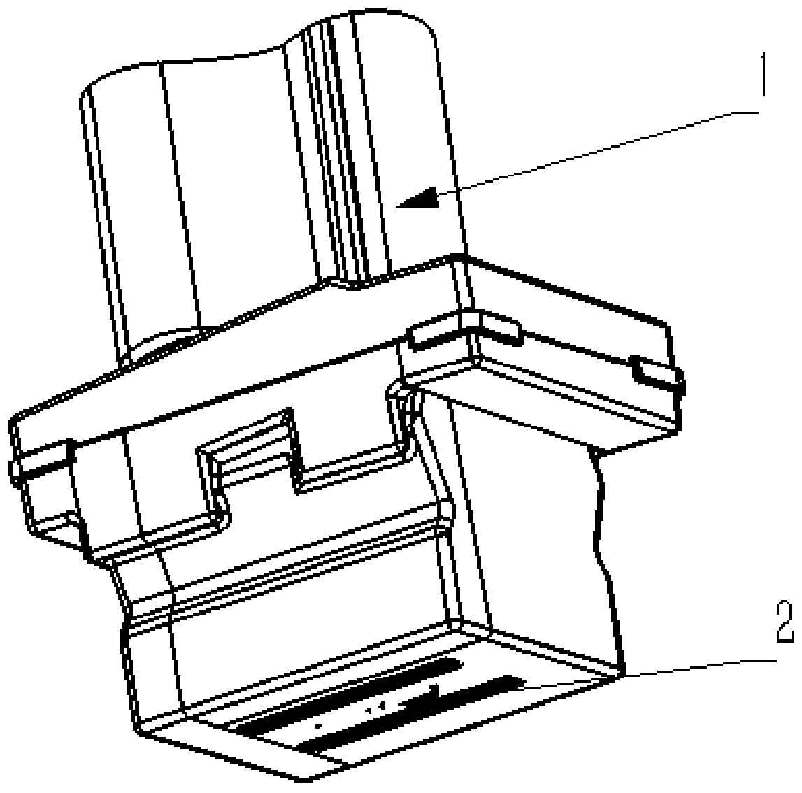
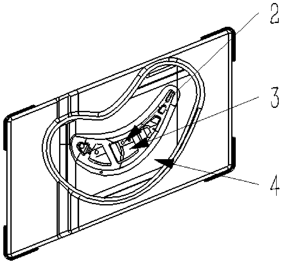
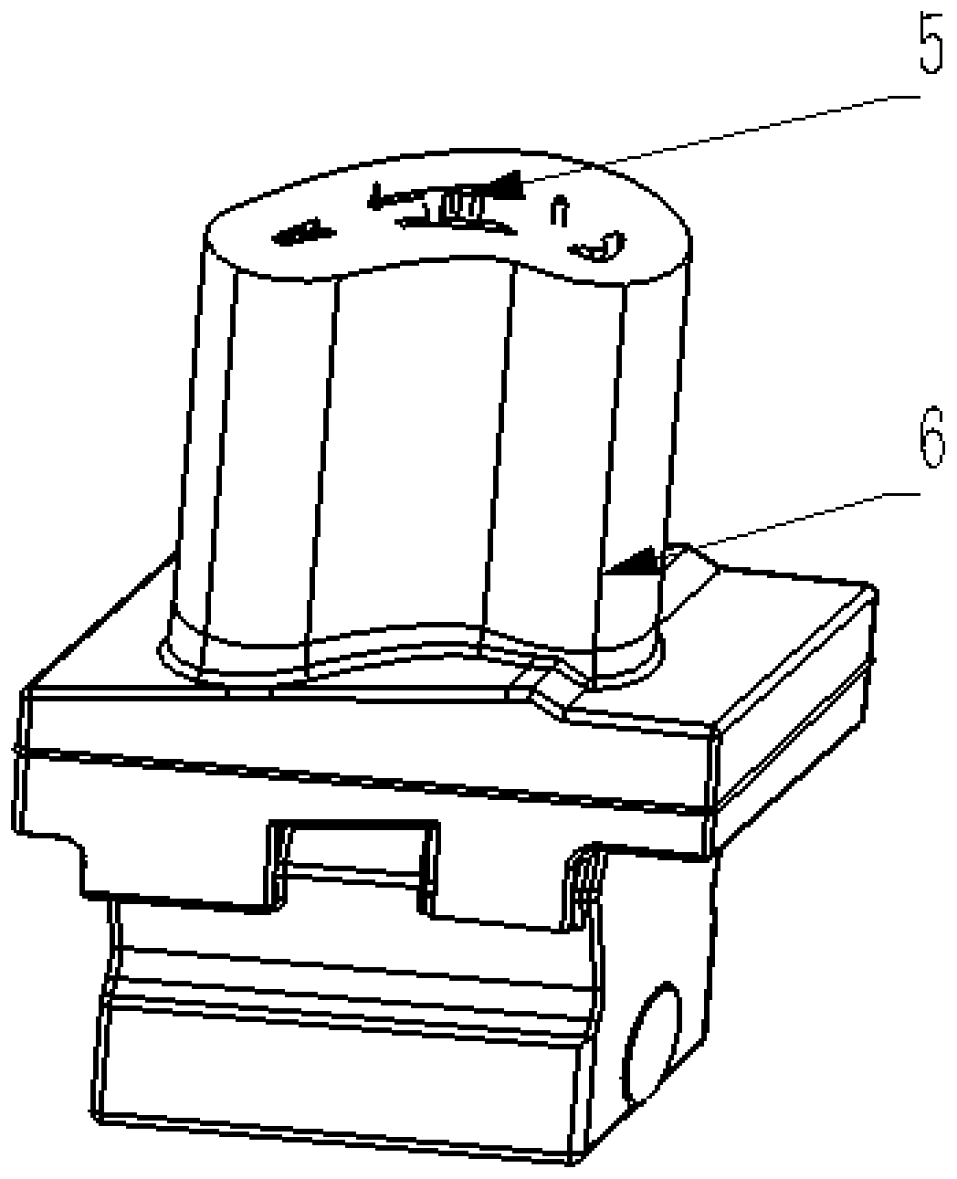
[0050] Use UG to design the 3D model of the resin mold, design the fixing holes, refer to figure 1 , figure 2 with image 3 , among which, 1 is the blade body; 2 is the fixing hole; 3 is the up and down straight core; 4 is the shell; 5 is the ceramic rod; The two-dimensional slice file with a thickness of 0.15mm is imported into the light-curing molding equipment to create a resin mold, and the excess resin and support are removed with industrial alcohol and dried.

[0051] 2) Select and insert the ceramic rod

[0052] For cores that run through the top and bottom, refer to figure 2 , Insert a ceramic rod into the fixing hole for interference fit, and fix the bottom end to the bottom of the resin mold with hot melt adhesive. After gel injection mold...

Embodiment 2

[0069] The difference from Example 1 is that, referring to figure 2 , For the core that is straight up and down, design a fixing hole at the bottom of the shell, insert the ceramic rod through it, and then fix it with hot melt adhesive. And for cores that are not straight up and down, such as Figure 4 with Figure 5 , the twist of the core is high, and when the ceramic rod with better rigidity cannot be inserted, fix holes are respectively set at the upper and lower ends of the mold, and the ceramic fiber 7 with good toughness is selected and twisted and inserted into the cavity. The ceramic fiber 7 is oxidized. Aluminum ceramic fiber or silicon carbide ceramic fiber is selected according to the material of the ceramic matrix, such as Image 6 shown, and glued in the fixing holes at both ends with AB glue. All the other processing steps are the same as in Example 1.


PUM


Abstract

The invention discloses a method for enhancing the creep resistance of a ceramic mold core through customization, belonging to the field of rapid casting of stereolithigraphy technology. The method comprises the following steps: 1) designing a resin mold prototype by using UG software, and manufacturing a light-cured resin mold by using the stereolithigraphy technology; 2) inserting specific ceramic rods or ceramic fibers into the resin mold; 3) designing a gel-casting ceramic slurry formula, and molding a ceramic shell blank by using a gel casting molding process; and 4) after vacuum freeze drying of a ceramic mold blank, burning off the resin prototype through roasting so as to obtain a complete integrated ceramic mold. The freeze-drying and roasting processes of the method can improve the deformation resistance of the mold core; the ceramic rods and the ceramic fibers can improve the toughness and strength of the mold core; and the creep resistance of the ceramic mold core is enhanced through customized manufacturing; and the method is suitable for actual production.

Description

technical field [0001] The invention belongs to the field of rapid casting based on light-curing molding technology, and in particular relates to a method for customizing and enhancing the creep resistance of ceramic casting cores. Background technique [0002] Rapid prototyping technology is a new generation of manufacturing technology developed in the late 1980s. Light-curing molding technology is the most mature method with the highest molding precision in rapid prototyping technology. It uses light-curing resin materials and uses three-dimensional lithography to manufacture prototypes. It can Form a part prototype of any complex shape. The combination of stereolithography technology and traditional investment casting process can greatly shorten the time required for investment pattern preparation, and save the time and cost of making molds for wax patterns. The complex mold is formed by light curing, and then the ceramic slurry is poured by gel injection molding technol...

Claims


Application Information

Patent Timeline
Patent Type & Authority Applications(China)
IPC IPC(8): C04B35/565C04B35/505C04B35/48C04B35/10C04B35/14C04B35/71C04B35/78C04B35/622B28B1/14B28B1/52B28B7/34B22C9/22B22C9/04B22D27/15
CPCB22C9/04B22C9/22B22D27/15B28B1/14B28B1/52B28B7/342B28B7/346B28B7/348C04B35/10C04B35/14C04B35/48C04B35/505C04B35/565C04B35/622C04B35/78C04B2235/5224C04B2235/5244C04B2235/6562C04B2235/6567
Inventor 鲁中良李涤尘王程冬苗恺陈义张凌锋卢秉恒
Owner XI AN JIAOTONG UNIV
Learn More