Eureka AIR delivers breakthrough ideas for toughest innovation challenges, trusted by R&D personnel around the world.

Turning and polishing integration machine for numerical control machining

A kind of mechanical processing and integrated machine technology, applied in the field of machinery, can solve the problems of small friction, unstable center of gravity, unfavorable use, etc., to achieve the effect of increasing the contact area, increasing friction, and ensuring stability

Active Publication Date: 2019-11-19
优尼斯工业服务(徐州)有限公司
View PDF12 Cites 3 Cited by
  • Summary
  • Abstract
  • Description
  • Claims
  • Application Information

AI Technical Summary

Problems solved by technology

[0005] The purpose of the present invention is to solve the shortcomings in the prior art, such as: the existing CNC grinding machine and CNC lathe are not synchronous, and the processed wood turning and grinding are processed separately, which is very inconvenient to use and low in production efficiency, which is not conducive to people The use of CNC lathes, and the friction between the CNC lathe and the ground during work is relatively small, the center of gravity is unstable, and it is easy to shake, resulting in low processing accuracy

Method used


Image

  • Turning and polishing integration machine for numerical control machining
  • Turning and polishing integration machine for numerical control machining
  • Turning and polishing integration machine for numerical control machining

Examples


Embodiment Construction

[0023] The following will clearly and completely describe the technical solutions in the embodiments of the present invention with reference to the accompanying drawings in the embodiments of the present invention. Obviously, the described embodiments are only some, not all, embodiments of the present invention.

[0024] In describing the present invention, it should be understood that the terms "upper", "lower", "front", "rear", "left", "right", "top", "bottom", "inner", " The orientation or positional relationship indicated by "outside", etc. is based on the orientation or positional relationship shown in the drawings, and is only for the convenience of describing the present invention and simplifying the description, rather than indicating or implying that the referred device or element must have a specific orientation, so as to Specific orientation configurations and operations, therefore, are not to be construed as limitations on the invention.

[0025] refer to Figure ...


PUM


Abstract

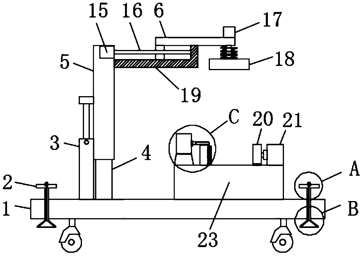
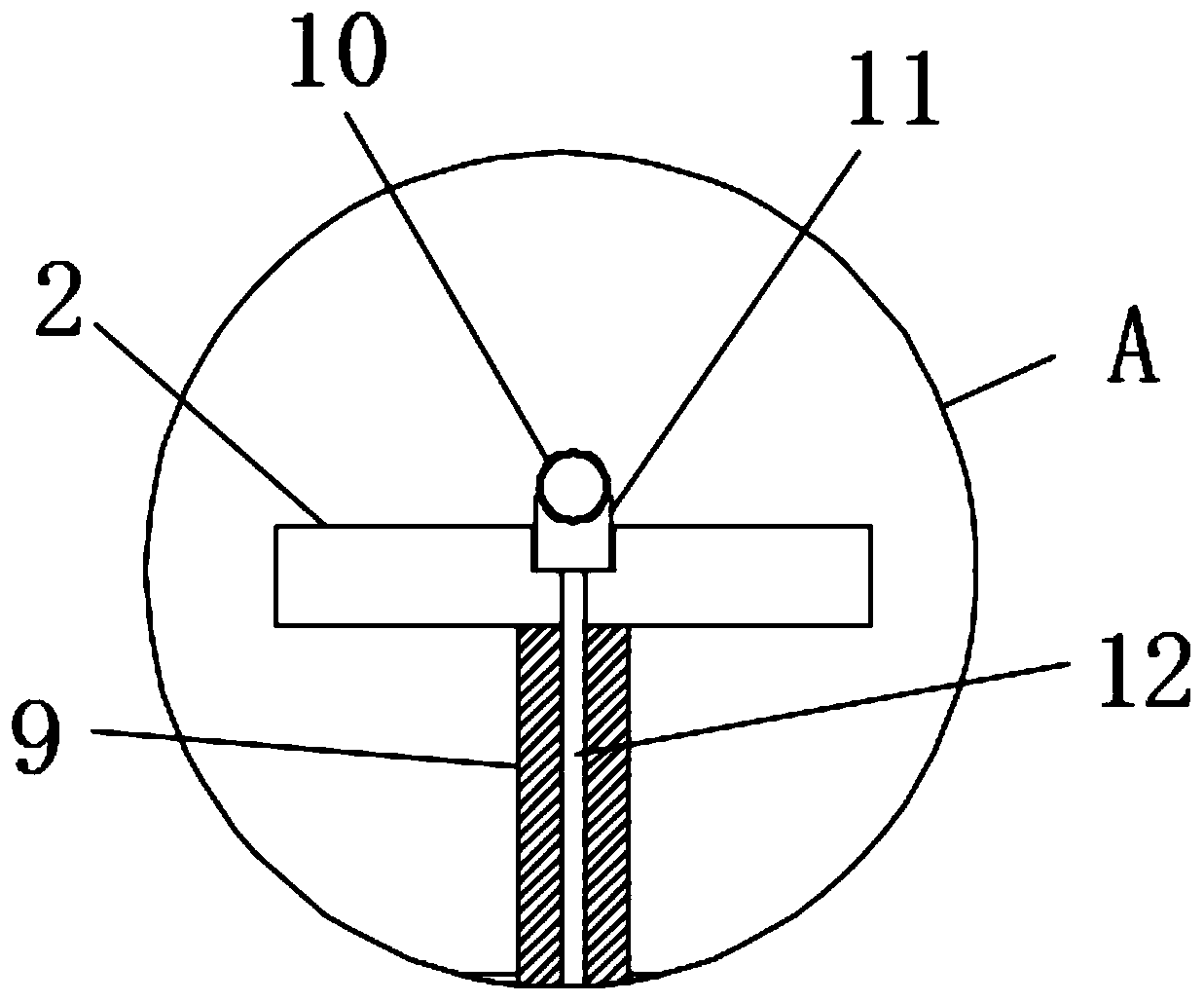
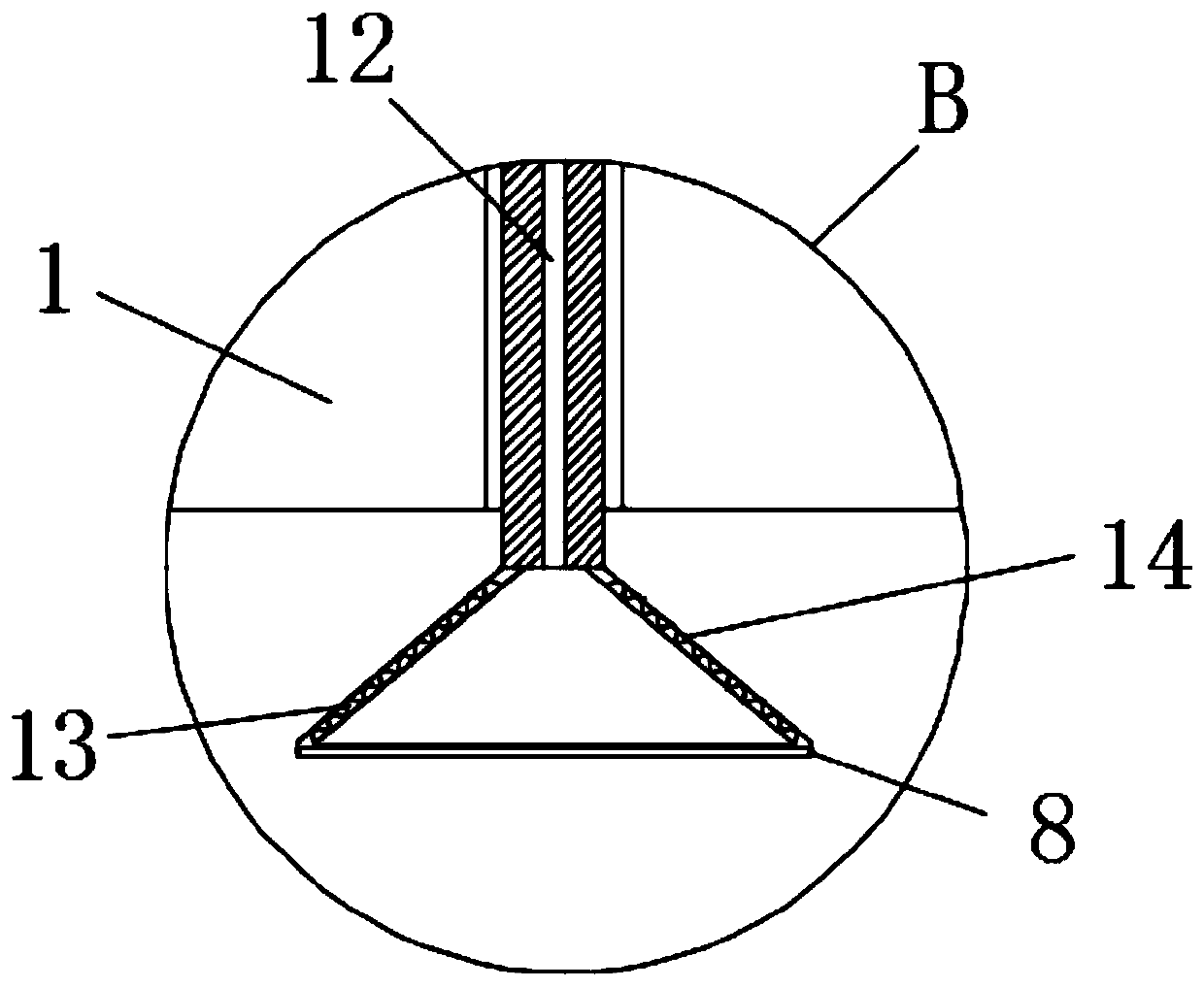
The invention discloses a turning and polishing integration machine for numerical control machining. The turning and polishing integration machine for numerical control machining comprises a base. A guide arm is fixedly connected to the center of the upper end face of the base, and a sliding arm is vertically arranged at the upper end of the guide arm. An adjusting rod is arranged on the left sidewall of the sliding arm, and the lower end of the adjusting rod and the upper end face of the base are fixedly connected. A driving mechanism is arranged on the right side wall of the upper end of the sliding arm. By the adoption of the turning and polishing integration machine for numerical control machining, after the mechanical device is placed, rotary handles are rotated, then threaded rods are driven to rotate and can downwards move in the base until suction disc suction ends at the lower ends of suction discs and the ground are closely attached with each other, the most of the air in the suction discs can be discharged through one-way holes, and therefore the pressure difference can be formed between the interior and the exterior of each suction disc, then the suction discs can be closely attached to the ground in a suction mode, the force of suction between the mechanical device and the ground can be increased, and the phenomena that due to the shift of the center of gravity, the mechanical device tilts in the working process, and the shift of the position of the mechanical device happens in the working process are avoided.

Description

technical field [0001] The invention relates to the field of mechanical technology, in particular to a turning and grinding integrated machine for numerical control machining. Background technique [0002] CNC machining refers to a process method for processing parts on CNC machine tools. The process regulations of CNC machine tool processing and traditional machine tool processing are generally consistent, but significant changes have also taken place. Digital information is used to control parts. It is an effective way to solve the problems of variable parts, small batches, complex shapes, and high precision and to achieve high-efficiency and automatic processing. CNC machining refers to the command issued by the control system to make the tool work. Various movements that meet the requirements, in the form of numbers and letters, express the technical requirements of the shape and size of the workpiece and the processing required by the processing technology. It generally...

Claims


Application Information

Patent Timeline
IPC IPC(8): B27C9/04B27C7/00B27C7/04B24B19/24B24B41/02B24B47/12B24B41/06
CPCB24B19/24B24B41/02B24B41/06B24B47/12B27C7/00B27C7/04B27C9/04
Inventor 于银龙
Owner 优尼斯工业服务(徐州)有限公司
Why Eureka
Eureka Blog
Learn More