Flue gas white smoke plume removing method for increasing heat energy utilization rate

A utilization rate and flue gas technology, applied in separation methods, chemical instruments and methods, gas treatment, etc., can solve the problems of low recycling rate, affecting the whitening of flue gas, waste of heat energy, etc. Condensation effect, effect of reducing investment amount

Inactive Publication Date: 2019-10-29
河南迪诺环保科技股份有限公司
View PDF20 Cites 4 Cited by
  • Summary
  • Abstract
  • Description
  • Claims
  • Application Information

AI Technical Summary

Problems solved by technology

[0007] However, in the above-mentioned prior art, the flue gas dewhitening device adopted, in the process of use, the flue gas discharge contains a large amount of heat energy, and the recycling rate is low, resulting in a certain degree of waste of heat energy, which affects the effect of flue gas dewhitening

Method used


Image

  • Flue gas white smoke plume removing method for increasing heat energy utilization rate
  • Flue gas white smoke plume removing method for increasing heat energy utilization rate
  • Flue gas white smoke plume removing method for increasing heat energy utilization rate

Examples


Embodiment 1

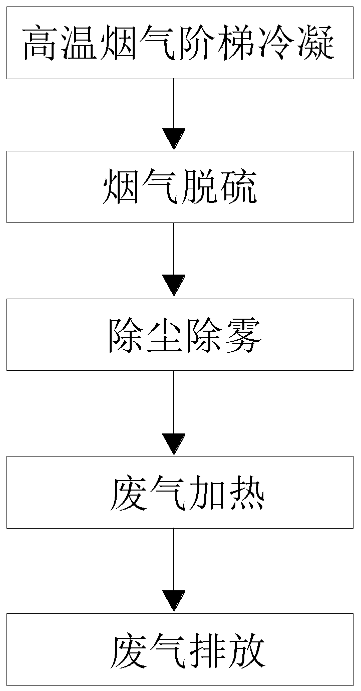
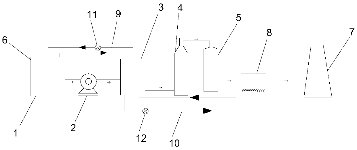
[0061] like figure 1 Shown, a kind of flue gas dewhitening method that improves thermal energy utilization rate, comprises the following steps:

[0062] S1: Stepwise condensation of high-temperature flue gas. The condenser is divided into a high-temperature chamber and a low-temperature chamber. The flue gas enters the high-temperature chamber and the low-temperature chamber in turn to condense. The cold water absorbs heat through the heat exchanger, and the steam condenses to achieve stepwise cooling;

[0063] S2: Flue gas desulfurization. The flue gas condensed by S1 enters the desulfurization tower. There are multi-layer desulfurization slurry spray devices distributed up and down inside the desulfurization tower. The acidic flue gas flows upward from the bottom and reversely contacts with the sprayed alkaline desulfurization slurry. Chemical neutralization reaction, the sulfurous acid generated falls into the bottom of the desulfurization tower for recycling;

[0064] S3:...

Embodiment 2

[0082] like Figure 1-6 As shown, the difference from Embodiment 1 is that the condenser 3 adopts segmental condensation, and the movable baffle 306 is controlled by the motor 303, thereby controlling the effective area of ​​ventilation. When the movable baffle 306 and the fixed baffle 305 are composed When it is a circle, the ventilation area is 0. At this time, it can effectively prolong the time that the high-temperature gas stays inside the condenser 3, further improve the condensation effect, make the flue gas release heat completely, and achieve the purpose of efficient recovery of heat energy; the flue gas is condensed The time that device 3 stays is t (unit is s), and the effective area of ​​ventilation is S (unit is m 2 ); then the flue gas heat energy recovery efficiency μ satisfies the following relationship:

[0083]

[0084]

[0085] In the above formula, α is a relational factor with a value range of 0.357-5.859; π is the circumference ratio, and d is the ...

Embodiment 3

[0088] like Figure 1-6 As shown, the difference from Embodiments 1 and 2 is that the particle diameter of the particulate matter in the flue gas satisfies:

[0089] D=(μV 0 h) 1 / 2 / ρWLT;

[0090] Where D is the particle diameter m of smoke particles, μ is the air viscosity Pa s, v 0 is the initial flow velocity m / s of the flue gas entering the dust and mist removal device, H is the height m of the dust and mist removal device, and ρ is the flue gas density mg / m 3 , W is the width m of the dust and mist removal device, and L is the length m of the dust and mist removal device.

[0091] v 0 The range of value is 6m / s~15m / s.

[0092] When the particle diameter of the particle meets the requirements of the above formula, the dust removal effect is the best; the particle in the flue gas settles to 5mg / m 3 Below, the water content is reduced to less than 15%, which meets the ultra-low emission standard of dust, improves the utilization of heat energy, and has a good dewhiten...


PUM


Abstract

The invention relates to a flue gas white smoke plume removing method for increasing the heat energy utilization rate. The flue gas white smoke plume removing method comprises the following steps: S1,high-temperature flue gas is subjected to stepped condensation, specifically, a condenser is divided into a high-temperature chamber and a low-temperature chamber, flue gas sequentially enters the high-temperature chamber and the low-temperature chamber to be condensed, steam is condensed, and thus stepped cooling is achieved; S2, the flue gas is subjected to desulfuration, specifically, the fluegas condensed in the step S1 enters a desulfurizing tower, acid flue gas flows upwards from the bottom and is in reverse contact with sprayed alkaline desulfuration slurry to be subjected to chemicalreaction, thus sulphurous acid is generated and falls into the bottom of the desulfurizing tower to be recovered; S3, dust removing and demisting are conducted, specifically, the flue gas subjected to desulfuration in the step S2 passes through an efficient micro-cyclone dust removing and demisting device, while liquid water with the grain size being 5 [mu]m or below is effective captured, vaporous water in the saturated flue gas is partially converted into liquid water, and the flue gas is transformed from the saturated state to the undersaturation state; S4, waste gas is heated, specifically, the flue gas subjected to dust removing and demisting in the step S3 is heated and warmed up through a water gas heat exchanger; and S5, the waste gas is discharged, specifically, after the flue gas is warmed up in the step S4, the saturability of the flue gas is reduced, and the flue gas is discharged into the atmosphere through a chimney.

Description

technical field [0001] The invention belongs to the technical field of boiler flue gas treatment technology, and in particular relates to a flue gas whitening method for improving heat energy utilization rate. Background technique [0002] The "white smoke" phenomenon occurs when industrial heating furnaces and power plant boilers discharge flue gas into the atmosphere, mainly because the hot flue gas meets the air, the temperature of the flue gas decreases, the moisture contained in it reaches supersaturation, and the water vapor condenses to form white mist . [0003] The existing conventional heating method (hot air flue gas mixed heating method or MGGH) can only eliminate the visual perception of white plume, cannot recover water, and cannot reduce the emission of pollutants and water vapor. PM2.5 carried in the flue gas , Hg, SO3 and other pollutants will not disappear after the flue gas is dried. For the atmospheric environment, the total amount of pollutant emissions...

Claims


Application Information

Patent Timeline
Patent Type & Authority Applications(China)
IPC IPC(8): B01D53/00B01D53/80B01D53/50B01D45/16
CPCB01D53/002B01D53/80B01D53/50B01D45/16B01D53/005B01D2258/0283
Inventor 李愉张志勇范长华孟常伟
Owner 河南迪诺环保科技股份有限公司
Why Eureka
Try Eureka