
Manufacturing method of water gap die sleeve

A manufacturing method and technology of die sets, which are applied in the field of making nozzle die sets, can solve the problems of long processing time of the nozzle die sets, unfavorable cost saving for enterprises, cracks of the nozzle die sets, etc., and achieve the solution of delayed fracture and fatigue fracture, resistance to Good rapid cooling and rapid heating performance, and the effect of reducing inventory

Inactive Publication Date: 2019-10-25
云南濮耐昆钢高温材料有限公司
View PDF5 Cites 1 Cited by
  • Summary
  • Abstract
  • Description
  • Claims
  • Application Information

AI Technical Summary

Problems solved by technology

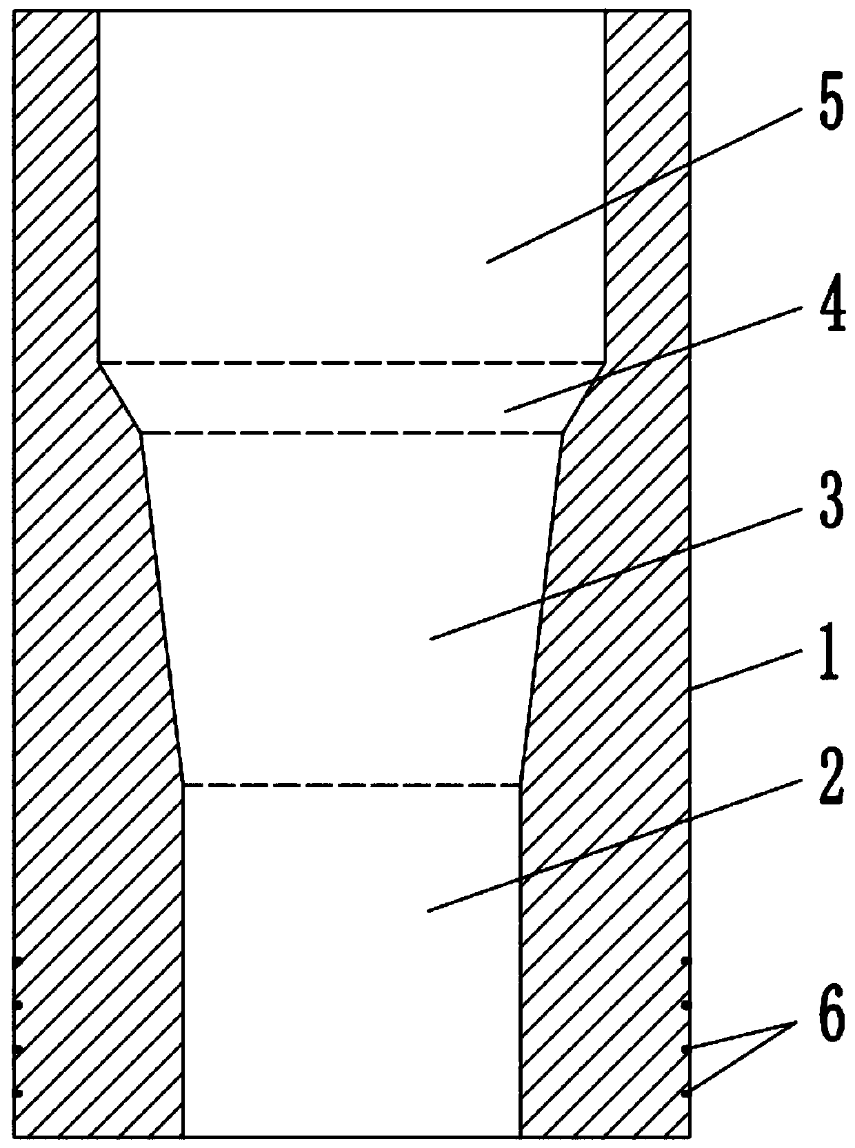
[0002] The nozzle mold is an important part of the ironmaking blast furnace system. The nozzle mold is easily damaged under the impact of high temperature and gravity.
Since the lower end of the nozzle mold sleeve is subject to high-temperature radiation and convective heat transfer, as well as the thermal stress caused by the extreme temperature difference between the inside and the outside, when the local area is subjected to excessive heat flow, the excessive thermal stress is likely to cause local cracking and damage to the nozzle mold sleeve.
Existing nozzle molds can usually only be used once, and they are replaced with new ones after partial damage, which cannot be reused. On the other hand, the processing time of nozzle molds is relatively long, and it takes at least nearly 30 hours to complete the processing, thus causing Great waste, not conducive to cost saving for enterprises

Method used


Image

  • Manufacturing method of water gap die sleeve

Examples


Embodiment 1

[0025] A. Select 20 parts of carbon, 25 parts of manganese, 15 parts of silicon, 1 part of tungsten, 20 parts of tin, 5 parts of aluminum, and 10 parts of iron, distribute them in a smelting furnace for melting, and cast them into bar blanks;

[0026] B. Take the cast and formed bar blank and forge it, forge the bar blank into a bar with a length of 430-440mm and a diameter of 200mm, and control the forging temperature at 650-700°C;

[0027] C. Turning, according to the size and structural characteristics of the die set, determine the basic parameters of the cutter head used for turning manufacturing, the turning process, and the speed of circumferential feed movement. First trim the bar, mill and remove 3mm from the bar surface, and cut off At both ends, the processing length of the bar is controlled to be 400-420mm, and then the forged bar is turned into a mold cover blank by using a precision lathe; the specific turning steps are:

[0028] C1. Drill a through hole aligned w...

Embodiment 2

[0034] A. Choose 27 parts of carbon, 30 parts of manganese, 25 parts of silicon, 3 parts of tungsten, 25 parts of tin, 13 parts of aluminum and 15 parts of iron;

[0035] B. Take the cast and formed bar blank and forge it, forge the bar blank into a bar with a length of 430-440mm and a diameter of 200mm, and control the forging temperature at 650-700°C;

[0036] C. Turning, according to the size and structural characteristics of the die set, determine the basic parameters of the cutter head used for turning manufacturing, the turning process, and the speed of circumferential feed movement. First trim the bar, mill and remove 3mm from the bar surface, and cut off At both ends, the processing length of the bar is controlled to be 400-420mm, and then the forged bar is turned into a mold cover blank by using a precision lathe; the specific turning steps are:

[0037] C1. Drill a through hole aligned with the shaft center of the bar with a precision lathe, then select one end of th...

Embodiment 3

[0043] A. Select 35 parts of carbon, 35 parts of manganese, 35 parts of silicon, 4 parts of tungsten, 30 parts of tin, 20 parts of aluminum and 20 parts of iron;

[0044] B. Take the cast and formed bar blank and forge it, forge the bar blank into a bar with a length of 430-440mm and a diameter of 200mm, and control the forging temperature at 650-700°C;

[0045] C. Turning, according to the size and structural characteristics of the die set, determine the basic parameters of the cutter head used for turning manufacturing, the turning process, and the speed of circumferential feed movement. First trim the bar, mill and remove 3mm from the bar surface, and cut off At both ends, the processing length of the bar is controlled to be 400-420mm, and then the forged bar is turned into a mold cover blank by using a precision lathe; the specific turning steps are:

[0046] C1. Drill a through hole aligned with the shaft center of the bar with a precision lathe, then select one end of th...


PUM

PropertyMeasurementUnit
pore sizeaaaaaaaaaa
lengthaaaaaaaaaa
lengthaaaaaaaaaa

Abstract

The invention discloses a manufacturing method of a water gap forming die sleeve. The method comprises the steps of A, blank selecting and casting, B, forging, C turning and D heat treatment. According to the manufacturing method of the water gap die sleeve, through burdening selection and manufacturing process optimization, the water gap die sleeve is low in linear change rate, high in strength and good in rapid cooling and heat resistance property after high-temperature burning, and the damage caused by frequent replacing of the water gap die sleeve is avoided; the forging process is adoptedfor machining, the strength of the water gap die sleeve is improved, the delayed fracture and the fatigue fracture of the water gap die sleeve can be solved, during use, connection is reliable, the die sleeve is not prone to cracking damage, the service life of the water gap die sleeve is prolonged, the water gap die sleeve can be recycled, repaired and then used, during recycling, the die sleevecan be recycled after the damage part is cut off according to the positioning ring line, the spare parts stock of an enterprise can be reduced, the enterprise production cost is reduced, and the economic benefit is improved.

Description

technical field [0001] The invention belongs to the technical field of metal smelting equipment, and in particular relates to a manufacturing method of a nozzle mold cover. Background technique [0002] The nozzle mold is an important part in the ironmaking blast furnace system. The nozzle mold is easily damaged under the impact of high temperature and gravity. Since the lower end of the nozzle mold sleeve is subject to high-temperature radiation and convective heat transfer, as well as the thermal stress caused by the extreme temperature difference between the inside and the outside, when the local area is subjected to excessive heat flow, the excessive thermal stress is likely to cause local cracking and damage to the nozzle mold sleeve. . Existing nozzle molds can usually only be used once, and they are replaced with new ones after partial damage, which cannot be reused. On the other hand, the processing time of nozzle molds is relatively long, and it takes at least near...

Claims


Application Information

Patent Timeline
Patent Type & Authority Applications(China)
IPC IPC(8): B23P15/00C22C30/00C22F1/00C21D9/00
CPCB23P15/00C21D9/0068C22C22/00C22C28/00C22C30/00C22F1/002C22F1/16
Inventor 项琼红吴谷桥徐文
Owner 云南濮耐昆钢高温材料有限公司
Learn More