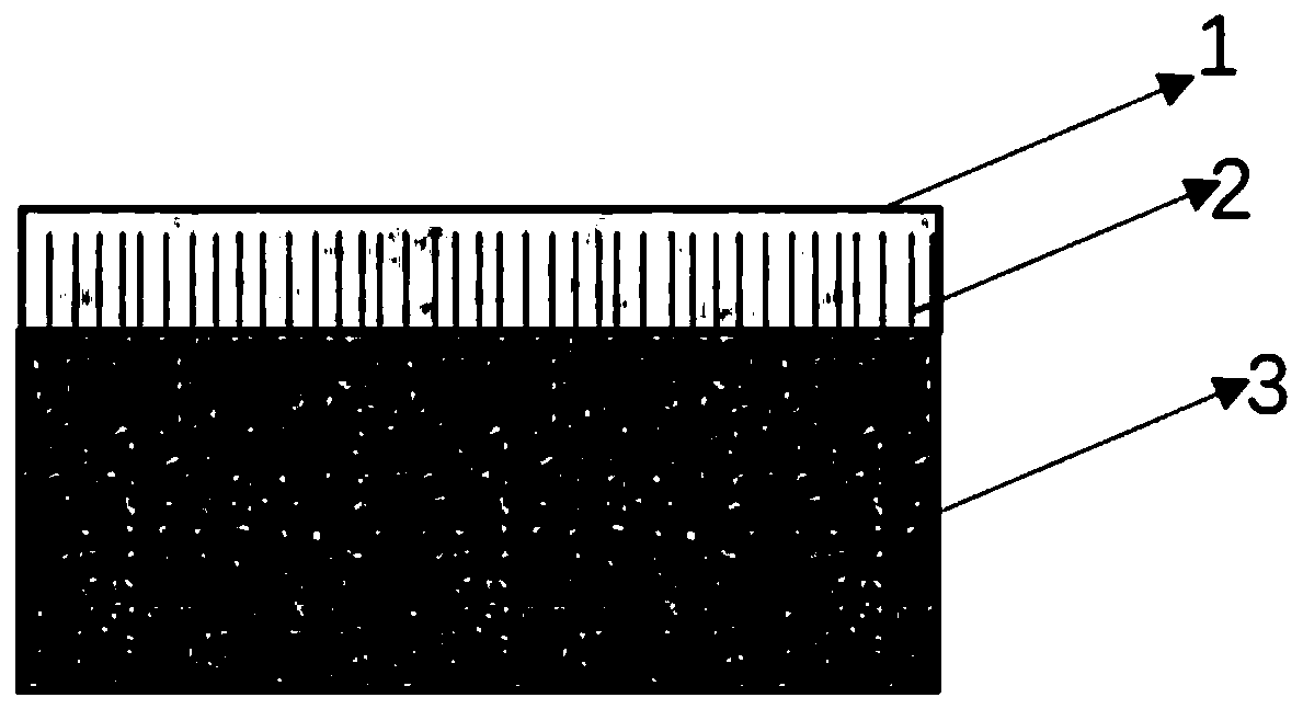
Fiber-reinforced Cf/SiC composite material welded joint
A technology of composite materials and welded joints, which is applied in the field of connection between composite materials and heterogeneous metals, and can solve the problems of brittle phase formation, fracture, and large interface stress at the interface
- Summary
- Abstract
- Description
- Claims
- Application Information
AI Technical Summary
Problems solved by technology
Method used
Image

Examples
Embodiment 1
[0022] S1. Place the Cf / SiC composite material in a NaOH solution with a concentration of 3mol / L;
[0023] S2. Heating the solution to 50°C, and reacting and corroding for 10 hours;
[0024] S3. Take out the sample, ultrasonically clean it, and dry it for use;
[0025] S4. Edit the metal area graphics in the fiber laser control software;
[0026] S5. Set the scanning speed in the software to 1-1000mm / s, the scanning distance to 0.01-1mm, and the laser power to 10-100%;
[0027] S6. Place the Cf / SiC composite material sample to be metallized on the laser processing platform, and place a metal foil with a thickness of 0.01-0.5mm on it;
[0028] S7. Adjust the focal length of the position and perform laser processing, the metal foil is vaporized and evaporated under the action of the laser, and sputtered onto the surface of the Cf / SiC composite material to obtain a metallized Cf / SiC composite material;
[0029] S8. The sample is polished and dried to obtain a final product.
...
Embodiment 2
[0032] S1. Place the Cf / SiC composite material in a NaOH solution with a concentration of 5mol / L;
[0033] S2. Heating the solution to 60°C, and reacting and corroding for 20 hours;
[0034] S3. Take out the sample, ultrasonically clean it, and dry it for use;
[0035] S4. Edit the metal area graphics in the fiber laser control software;
[0036] S5. Set the scanning speed in the software to 1-1000mm / s, the scanning distance to 0.01-1mm, and the laser power to 10-100%;
[0037] S6. Place the Cf / SiC composite material sample to be metallized on the laser processing platform, and place a metal foil with a thickness of 0.01-0.5mm on it;
[0038] S7. Adjust the focal length of the position and perform laser processing, the metal foil is vaporized and evaporated under the action of the laser, and sputtered onto the surface of the Cf / SiC composite material to obtain a metallized Cf / SiC composite material;
[0039] S8. The sample is polished and dried to obtain a final product.
...
Embodiment 3
[0042] S1. Place the Cf / SiC composite material in a NaOH solution with a concentration of 7mol / L;
[0043] S2. Heating the solution to 70°C, and reacting and corroding for 30 hours;
[0044] S3. Take out the sample, ultrasonically clean it, and dry it for use;
[0045] S4. Edit the metal area graphics in the fiber laser control software;
[0046] S5. Set the scanning speed in the software to 1-1000mm / s, the scanning distance to 0.01-1mm, and the laser power to 10-100%;
[0047] S6. Place the Cf / SiC composite material sample to be metallized on the laser processing platform, and place a metal foil with a thickness of 0.01-0.5mm on it;
[0048] S7. Adjust the focal length of the position and perform laser processing, the metal foil is vaporized and evaporated under the action of the laser, and sputtered onto the surface of the Cf / SiC composite material to obtain a metallized Cf / SiC composite material;
[0049] S8. The sample is polished and dried to obtain a final product.
...
PUM
| Property | Measurement | Unit |
|---|---|---|
| Thickness | aaaaa | aaaaa |
Abstract
Description
Claims
Application Information
 - R&D
- Intellectual Property
- Life Sciences
- Materials
- Tech Scout
- Unparalleled Data Quality
- Higher Quality Content
- 60% Fewer Hallucinations
Browse by: Latest US Patents, China's latest patents, Technical Efficacy Thesaurus, Application Domain, Technology Topic, Popular Technical Reports.
© 2025 PatSnap. All rights reserved.Legal|Privacy policy|Modern Slavery Act Transparency Statement|Sitemap|About US| Contact US: help@patsnap.com