A high-temperature industrial flue gas desulfurization and denitrification treatment method

A high-temperature industry, desulfurization and denitrification technology, applied in gas treatment, separation methods, chemical instruments and methods, etc., can solve the problem of less research on building and improving reaction sufficiency, low utilization rate of reagents, and short duration of reaction process, etc. problems, to achieve the effect of less single dosage, increased contact probability, and high use efficiency

Active Publication Date: 2021-12-07
YUZHOU HENGLILAI ALLOY CO LTD
View PDF0 Cites 0 Cited by
  • Summary
  • Abstract
  • Description
  • Claims
  • Application Information

AI Technical Summary

Problems solved by technology

[0003] At present, the research on desulfurization and denitrification treatment of industrial flue gas and the market technology mainly focus on the selection and mixed use of desulfurization and denitrification reaction solutions, the control of reaction time and conditions, the utilization of high-temperature flue gas waste heat, and the treatment and utilization of products after desulfurization and denitrification reactions. However, there are few studies on the improvement of flue construction for high-temperature flue gas desulfurization and denitrification treatment, the control of the reaction link, and the adequacy of the reaction; the overall desulfurization and denitrification link has high construction costs such as flue flue and low practical rate , The amount of reagent required for desulfurization and denitrification is large and the complete utilization rate of the reagent amount is low, the reaction process lasts for a short time and cannot fully react, and the desulfurization and denitrification effect is poor, etc.

Method used


Image

  • A high-temperature industrial flue gas desulfurization and denitrification treatment method
  • A high-temperature industrial flue gas desulfurization and denitrification treatment method
  • A high-temperature industrial flue gas desulfurization and denitrification treatment method

Examples


Embodiment 1

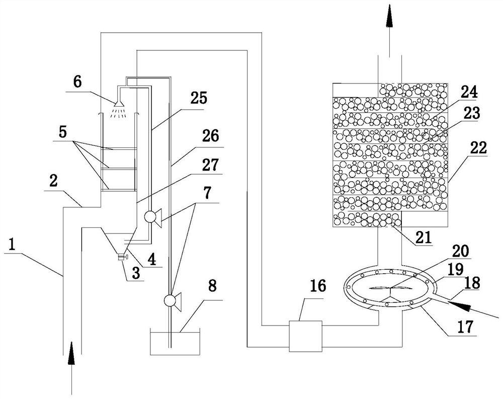
[0040] First build the desulfurization and denitrification chimney pipeline with spray head 6, low-lying groove 4, mixing tank 17, denitration chimney pipeline 22;

[0041] Then build the flue absorption layer 5:

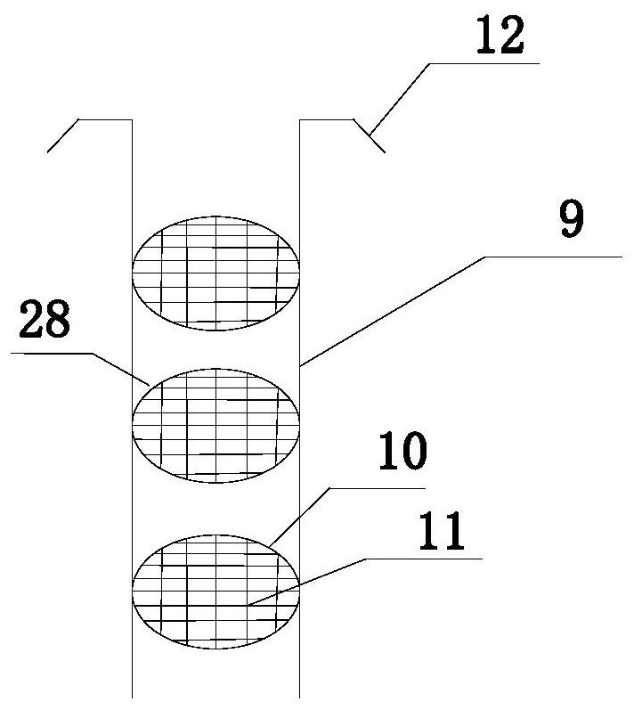
[0042] A plurality of reinforcement bars 11 are welded in the ring 10, and the reinforcement bars 11 are arranged horizontally and vertically to obtain a circular reinforcement grid 28, and the outer diameter of the reinforcement grid 28 matches the inner diameter of the flue;

[0043] 3-5 circular reinforcement grids 28 are welded on three vertical steel bars arranged in a circle, and then one end of the vertical steel bars is bent into a hook shape to obtain a steel bar frame 9;

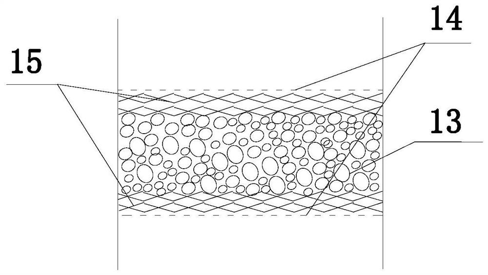
[0044] Lay a layer of metal mesh 14 on the steel grid, then lay a layer of asbestos 15 on the metal mesh 14, lay a layer of activated carbon 13 on the asbestos 15, and spread a layer of asbestos 15 on the activated carbon 13, and finally lay a layer of asbestos on the asbestos 15 Lay on...

Embodiment 2

[0051] No sulfur dioxide absorbing layer is used in the desulfurization process, and the flue gas is directly sprayed with a nozzle, and the other conditions are the same as in Example 1.

Embodiment 3

[0053] Before denitrification, the ammonia gas and flue gas were mixed without using a gas mixing tank, and the two gases were directly passed into the denitrification chimney pipe, and other conditions were the same as in Example 1.


PUM

PropertyMeasurementUnit
pore sizeaaaaaaaaaa
diameteraaaaaaaaaa
pore sizeaaaaaaaaaa

Abstract

The invention relates to a high-temperature industrial flue gas desulfurization and denitrification treatment method. The flue gas denitrification equipment mainly includes the following parts: a sulfur dioxide absorption layer, a sodium hydroxide solution spray system, a gas mixing tank, and a denitrification chimney pipe. The method utilizes the absorption of sulfur dioxide by sodium hydroxide, the high specific surface area of ​​the absorption layer, the rapid mixing of the gas mixing tank and the unique structure of the denitrification chimney pipe to improve the desulfurization and denitrification effect. Therefore, in the process of desulfurization and denitrification, the method fully utilizes the sodium hydroxide solution and ammonia gas, reduces the waste of reagents, reduces the treatment cost, and improves the effect of desulfurization and denitrification.

Description

technical field [0001] The invention relates to the field of waste gas treatment, in particular to a desulfurization and denitrification treatment method for high-temperature industrial flue gas. Background technique [0002] Flue gas is mainly produced from the exhaust gas generated by the combustion of fossil fuels such as power plants, and its main components are: nitrogen, carbon dioxide, water vapor, sulfur dioxide, nitrogen oxides and inert gases that are not combustible in the air. Among them, sulfur dioxide is a colorless gas with a strong pungent smell and is one of the main pollutants in the atmosphere. Since coal and petroleum typically contain sulfur compounds, sulfur dioxide is formed when burned. When sulfur dioxide dissolves in water, it will form sulfurous acid, which is the main component of acid rain. When sulfurous acid is further oxidized, it will form sulfuric acid, causing the acidification of the environment. There are many types of nitrogen oxides, ...

Claims


Application Information

Patent Timeline
Patent Type & Authority Patents(China)
IPC IPC(8): B01D53/50B01D53/56B01D53/78B01D53/79B01D53/90B01D53/96
CPCB01D53/504B01D53/78B01D53/79B01D53/8631B01D53/90B01D53/96B01D2251/2062B01D2251/304B01D2251/604B01D2258/0283
Inventor 许翠英金严李超
Owner YUZHOU HENGLILAI ALLOY CO LTD
Why Eureka
Try Eureka