
IGBT power device and manufacturing method thereof

A technology for power devices and manufacturing methods, which is applied in semiconductor/solid-state device manufacturing, semiconductor devices, electrical components, etc., and can solve problems such as breakdown voltage effects

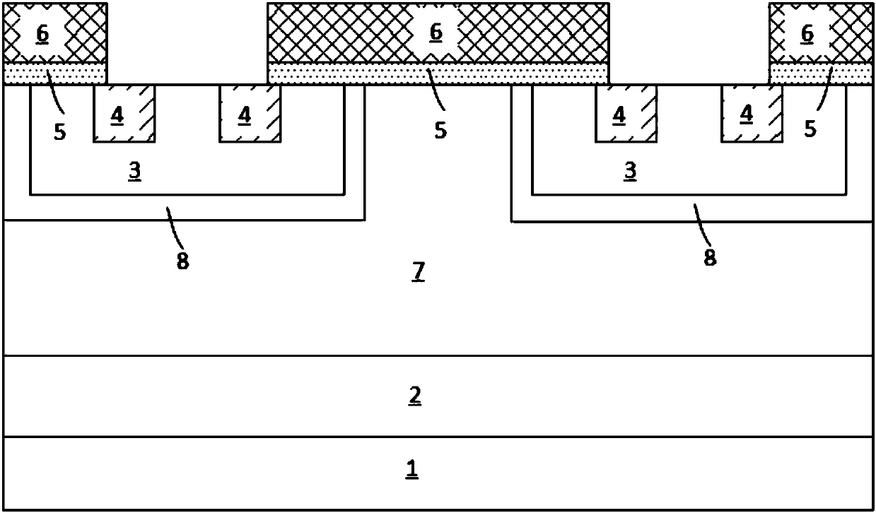
Inactive Publication Date: 2019-08-16
SUZHOU ORIENTAL SEMICONDUCTOR CO LTD
View PDF6 Cites 11 Cited by
  • Summary
  • Abstract
  • Description
  • Claims
  • Application Information

AI Technical Summary

Problems solved by technology

[0004] In view of this, the purpose of the present invention is to provide a kind of IGBT power device, to solve the problem in the prior art by adjusting the doping concentration of the n-type hole charge blocking region to optimize the forward conduction voltage drop and turn-off time of the IGBT power device The problem that affects the breakdown voltage when

Method used


Image

  • IGBT power device and manufacturing method thereof
  • IGBT power device and manufacturing method thereof
  • IGBT power device and manufacturing method thereof

Examples


Embodiment Construction

[0053] In order to make the purpose, technical solution and advantages of the present invention clearer, the technical solution of the present invention will be fully described below in a specific manner in conjunction with the drawings in the embodiments of the present invention. Apparently, the described embodiments are some embodiments of the present invention, rather than all embodiments. Based on the embodiments of the present invention, all other embodiments obtained by persons of ordinary skill in the art without making creative efforts, All fall within the protection scope of the present invention.

[0054]It should be understood that terms such as "having", "comprising" and "including" used herein do not denote the presence or addition of one or more other elements or combinations thereof. At the same time, in order to clearly illustrate the specific implementation of the present invention, the schematic diagrams listed in the accompanying drawings of the description ...


PUM


Abstract

The invention belongs to the technical field of semiconductor power devices, and particularly discloses an IGBT (Insulated Gate Bipolar Transistor) power device. The device comprises: a p-type collector region; an n-type field stop region located on the p-type collector region; an n-type drift region located on the n-type field stop region; a plurality of first grooves, a second groove is arrangedat the lower portion of each first groove; gate structures located in the first grooves and the second grooves; p-type body regions located between adjacent first grooves; n-type emitter regions located in the p-type body regions; and n-type hole charge barrier regions located between the n-type drift region and the p-type body regions. The position of the electric field peak value of the IGBT power device in the reverse bias state can be regulated to allow the IGBT power device to have the smaller forward conduction voltage drop and the shorter turn-off time under the same breakdown voltage.

Description

technical field [0001] The invention belongs to the technical field of semiconductor power devices, in particular to an IGBT power device and a manufacturing method thereof. Background technique [0002] The Insulated Gate Bipolar Transistor (IGBT) power device is a device composed of a MOS transistor and a bipolar transistor. Its input is a MOS transistor and its output is a PNP transistor. It combines these two devices The advantages of MOS transistors, which not only have the advantages of small driving power and fast switching speed of MOS transistors, but also have the advantages of low saturation voltage drop and large capacity of bipolar transistors, have been more and more widely used in modern power electronics technology, especially occupying The dominance of high-frequency and medium-power tube applications has been confirmed. [0003] The schematic diagram of the cross-sectional structure of the IGBT power device of the prior art planar structure is as figure 1...

Claims


Application Information

Patent Timeline
IPC IPC(8): H01L29/739H01L29/40H01L21/331
CPCH01L29/7397H01L29/407H01L29/66348H01L29/7396H01L29/1095H01L29/42376H01L29/083H01L29/417H01L29/0821H01L29/41708
Inventor 刘伟刘磊毛振东袁愿林
Owner SUZHOU ORIENTAL SEMICONDUCTOR CO LTD
Learn More