Weak magnetic field excitation three-coil detection device
A technology of exciting coils and three coils, which is applied in the direction of circuit devices, transportation and packaging, charging stations, etc., can solve the problems of increasing the withstand voltage requirements and anti-interference requirements of signal detection circuits, high-voltage breakdown, etc., and achieve single-point position Effect of detection and auxiliary guidance, reduction of port voltage, reduction of current intensity
- Summary
- Abstract
- Description
- Claims
- Application Information
AI Technical Summary
Problems solved by technology
Method used
Image
Examples
Embodiment 1
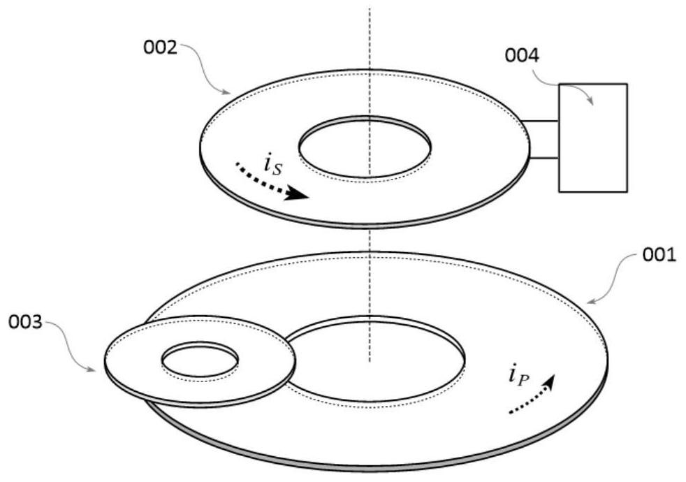
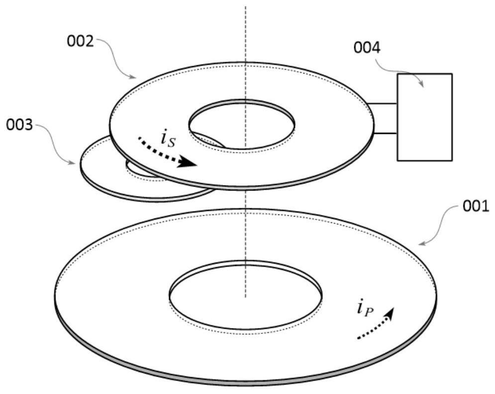
[0100] In order to illustrate the weak magnetic field excitation three-coil detection device of this embodiment, a detailed description will be given below in conjunction with the accompanying drawings. The primary side excitation coil 001 is used to generate a positioning magnetic field, and the secondary side response coil 002 on the other side is connected to the response coil resonant network 004, wherein the detection unit 003 is located on the side of the primary side excitation coil, such as figure 1 shown; or on the side of the secondary response coil, such as figure 2 shown. The detection unit 003 is a detection coil, or a detection sub-unit is formed by connecting multiple detection coils, and the induced electromotive force v of the detection unit 003 3 It can be calculated by the following formula:
[0101] v 3 =jM 13 ωI p +j M 23 ωI s (2)
[0102]Among them, ω is the excitation current I in the primary excitation coil 001 p The angular frequency of M 1...
Embodiment 2
[0113] The difference with embodiment 1 only lies in:
[0114] The induced electromotive force v shown in analytical formula (5) 3 When the positions of the primary excitation coil 001 and the secondary response coil 002 change, regardless of whether the detection unit 003 is installed on the primary excitation coil side or on the secondary response coil side, M 13 The trend of change and M 23 M 12 The changing trends are different. In order to make the induced electromotive force v of the detection unit 003 3 Simplified with the position change trend, the weak magnetic field excitation three-coil detection device of this embodiment installs the detection unit 003 on the side of the primary side excitation coil, that is, the relative position of the detection unit 003 and the primary side excitation coil 001 is fixed, so that in any case m 13 stable. By applying an excitation current at or near the resonance frequency to the primary excitation coil 001, L s ≈0, so that ...
Embodiment 3
[0122] The difference with embodiment 2 only lies in:
[0123] In order to reduce the induced electromotive force v 3 Influenced by the bias constant C, in this embodiment, the detection unit 003 is installed at the induction blind spot of the primary excitation coil 001, that is, the position where the magnetic induction intensity is about 0, so that under any circumstances M 13 ≈0, the simplified formula (6) makes the induced electromotive force v of the detection unit 003 3 With the monotonous change of the relative position of the excitation coil 001 of the primary side and the response coil 002 of the secondary side, the excitation current is reduced, the detection signal is amplified, and the interference of the excitation current of the primary side is reduced.
[0124] at this time:
[0125]
[0126] The relative position coordinates (x, y) of the secondary side response coil 002 and the primary side excitation coil 001 are calculated by the coil mutual inductance...
PUM
 Abstract
Description
Claims
Application Information
 - R&D
- Intellectual Property
- Life Sciences
- Materials
- Tech Scout
- Unparalleled Data Quality
- Higher Quality Content
- 60% Fewer Hallucinations
Browse by: Latest US Patents, China's latest patents, Technical Efficacy Thesaurus, Application Domain, Technology Topic, Popular Technical Reports.
© 2025 PatSnap. All rights reserved.Legal|Privacy policy|Modern Slavery Act Transparency Statement|Sitemap|About US| Contact US: help@patsnap.com


