Composite Strengthening Method for Large-area Flat Coatings
A large-area, flat technology, applied in the field of large-area flat coating composite strengthening, can solve the problems of insufficient coating film/base bonding force, weak film/base bonding force, poor mechanical properties of components, etc., to improve hardness, increase The effect of interfacial adhesion, fatigue strength and wear and corrosion resistance
- Summary
- Abstract
- Description
- Claims
- Application Information
AI Technical Summary
Problems solved by technology
Method used
Image

Examples
Embodiment 1
[0047] The composite strengthening method of large-area flat coating comprises the following steps:
[0048] S1. Ultrasonic vibration assisted peripheral milling (suitable for large-sized workpieces)
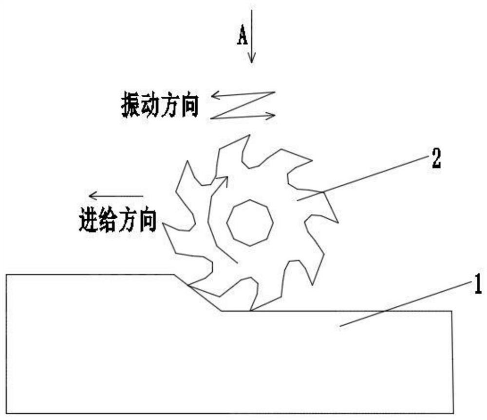
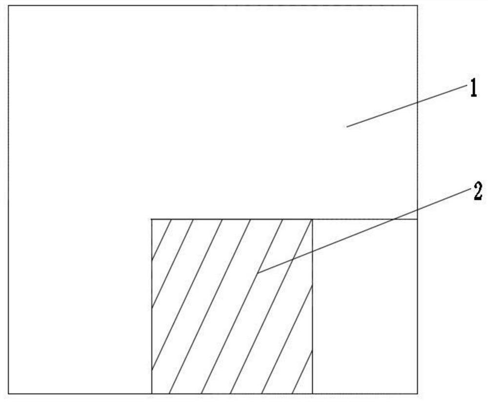
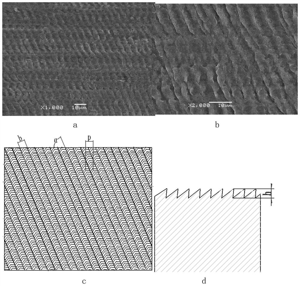
[0049] as attached figure 1 , 2 As shown, the workpiece 1 is fixed and clamped on the milling machine table; the peripheral milling cutter 2 rotates around the main shaft, and at the same time makes a feed motion along the horizontal direction, and makes a small reciprocating vibration with a fixed frequency along the feed direction, forming a as attached image 3 The shown regular distribution of micron-sized furrow-shaped 3D microstructures.
[0050] Set the process parameters as follows:
[0051] Spindle rotation speed: 5000r / min;
[0052] Milling cutter helix angle: 25°;
[0053] Circumferential milling cutter feed speed: 40mm / min;
[0054] Ultrasonic vibration amplitude: 7 microns;
[0055] Ultrasonic vibration frequency: 20KHz.
[0056] In the obtained three-dimen...
Embodiment 2
[0070] as attached Figure 5 As shown, in step S1, the workpiece 1 is clamped on the worktable of the milling machine and follows the worktable along the feeding direction of the circumferential milling cutter 2 to make a small reciprocating vibration with a fixed frequency; the circumferential milling cutter 2 rotates around the main shaft and simultaneously Do feed movement, form specific regular distribution of nano-scale micro-geometric topography on the processing surface (suitable for small-sized workpieces).
[0071] Steps S2, S3, and S4 are the same as those in Embodiment 1.
experiment example 1
[0077] Sample 1: the workpiece processed by milling in step S1.
[0078] Sample 2: The workpiece processed by ordinary circumferential milling.
[0079] The roughness of the sample surface was measured, and the results were as follows: Figure 6 shown. It can be seen that at the same feed rate, the roughness of ultrasonic vibration milled parts is much lower than that of ordinary milled parts.
PUM
 Abstract
Description
Claims
Application Information
 - R&D
- Intellectual Property
- Life Sciences
- Materials
- Tech Scout
- Unparalleled Data Quality
- Higher Quality Content
- 60% Fewer Hallucinations
Browse by: Latest US Patents, China's latest patents, Technical Efficacy Thesaurus, Application Domain, Technology Topic, Popular Technical Reports.
© 2025 PatSnap. All rights reserved.Legal|Privacy policy|Modern Slavery Act Transparency Statement|Sitemap|About US| Contact US: help@patsnap.com