Anisotropic electrically-conductive adhesive agent
A conductive adhesive, anisotropic technology, applied in the direction of conductive adhesive, conductive connection, adhesive, etc., can solve the problems of poor electrical connection, difficulty in miniaturization, flexibility, and low versatility of the substrate, and achieve excellent durability Effects of heat and light resistance
- Summary
- Abstract
- Description
- Claims
- Application Information
AI Technical Summary
Problems solved by technology
Method used
Image

Examples
Embodiment
[0053] Hereinafter, examples of the present invention will be described. In this example, various anisotropic conductive adhesives were produced. Then, the blue LED chip was mounted on the substrate using an anisotropic conductive adhesive, and the LED mounting sample A was produced, and the push-out strength was measured at the initial stage and after the high-temperature, high-humidity continuous lighting test, and the heat resistance was evaluated. In addition, UV LED chips were mounted on the substrate using an anisotropic conductive adhesive, LED mounting sample B was produced, and the forward direction was measured at the initial stage, after the TCT (Temperature Cycling Test) test, and after the high-temperature, high-humidity continuous lighting test. Voltage, heat resistance and light resistance were evaluated. However, the present invention is not limited to these examples.
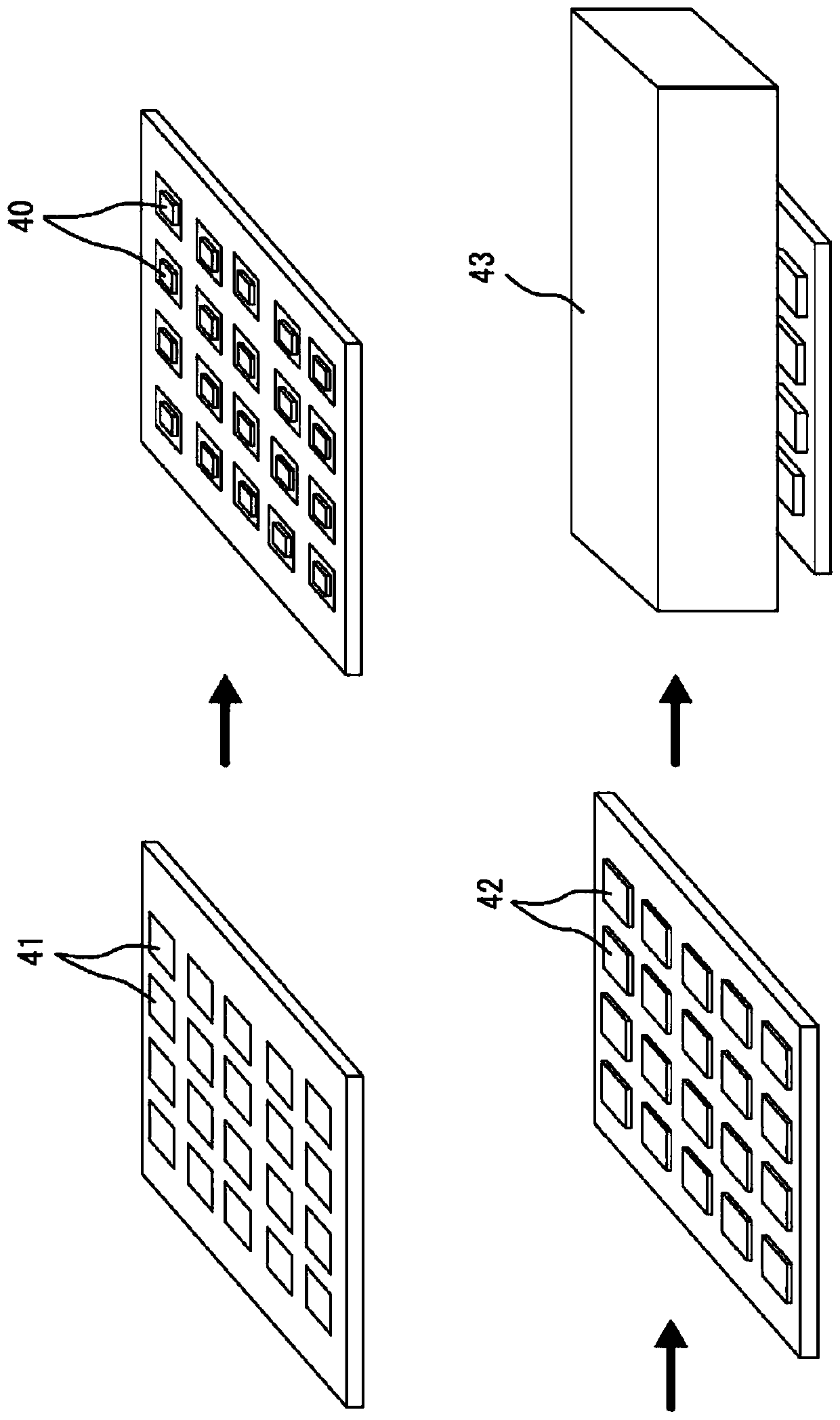
[0054] [Production of LED mounting samples]
[0055] figure 2 It is a figure for demons...
Embodiment 2
[0065] As shown in Table 1, weigh and add 100 mass parts of water glass (sodium silicate No. 3 shown in JIS K1408) and 10 mass parts of resin core conductive particles (average particle diameter 5 μm, nickel-plated, resin core particles (Nippon Chemical Co., Ltd. EH cores)) were stirred with a planetary mixer at 2000rpm / 2min to produce an anisotropic conductive adhesive. Other than that, LED mounting samples A and B were produced similarly to Example 1.
Embodiment 3
[0067] As shown in Table 1, 100 parts by mass of water glass (sodium silicate No. 3 listed in JIS K1408), 30 parts by mass of solder particles (particle size 10 μm to 25 μm, melting point 180°C, manufactured by Senju Metal Industry Co., Ltd.) and 5 parts by mass of resin core conductive particles (average particle diameter 5 μm, nickel-plated, resin core particles (EH core manufactured by Nippon Chemical Co., Ltd.)) were stirred at 2000 rpm / 2min with a planetary mixer to prepare an anisotropic conductive adhesive. Other than that, LED mounting samples A and B were produced similarly to Example 1.
PUM
| Property | Measurement | Unit |
|---|---|---|
| Particle size | aaaaa | aaaaa |
| Melting point | aaaaa | aaaaa |
| Particle size | aaaaa | aaaaa |
Abstract
Description
Claims
Application Information
 - R&D
- Intellectual Property
- Life Sciences
- Materials
- Tech Scout
- Unparalleled Data Quality
- Higher Quality Content
- 60% Fewer Hallucinations
Browse by: Latest US Patents, China's latest patents, Technical Efficacy Thesaurus, Application Domain, Technology Topic, Popular Technical Reports.
© 2025 PatSnap. All rights reserved.Legal|Privacy policy|Modern Slavery Act Transparency Statement|Sitemap|About US| Contact US: help@patsnap.com