Photoelectric composite cable and application thereof in 5G front-haul network

An optoelectronic composite cable and optoelectronic hybrid technology, which is applied to power cables, power cables, cables and other directions including optical transmission elements, can solve the problems of high labor, material resources, and high costs, and achieve low overall cost, easy construction, and space occupation. small effect

Pending Publication Date: 2019-07-05
JIANGSU HENGTONG PHOTOELECTRIC
View PDF0 Cites 2 Cited by
  • Summary
  • Abstract
  • Description
  • Claims
  • Application Information

AI Technical Summary

Problems solved by technology

The existing base station deployment adopts the drop-in cable and generally adopts the form of separating the optical cable and the cable for laying. During the laying process, a lot of manpower and material resources are required for laying, and the cost is relatively high.

Method used


Image

  • Photoelectric composite cable and application thereof in 5G front-haul network
  • Photoelectric composite cable and application thereof in 5G front-haul network
  • Photoelectric composite cable and application thereof in 5G front-haul network

Examples


Embodiment 1

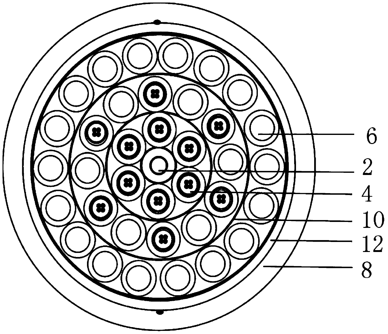
[0028] refer to figure 1 As shown, the present invention discloses a photoelectric composite cable, comprising a central strengthening member 2, an optical signal layer coated outside the central strengthening member 2, an optoelectronic hybrid layer covering the above optical signal layer, and a photoelectric hybrid layer covering the above optical signal layer. For the electrical signal layer outside the mixed layer, wrapping tape 10 is provided on the outer side of the above-mentioned optical signal layer, photoelectric mixed layer and electrical signal layer, and the outer side of the wrapping tape of the above-mentioned electrical signal layer is covered with an aluminum strip 12, and the outer side of the above-mentioned aluminum strip 12 Cover the sheath layer 8 .

[0029] The optical signal layer has six optical units 4 centered on the central stiffener 2 and twisted along the extending direction of the central stiffener 2 .

[0030] The photoelectric hybrid layer has...

Embodiment 2

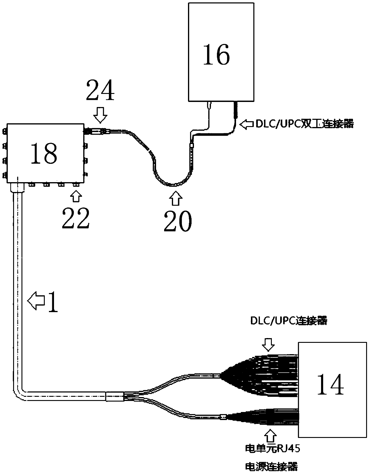
[0044] This embodiment discloses the application of a photoelectric composite cable in the 5G fronthaul network. The photoelectric composite cable obtained in the seventh step of Embodiment 1 is applied between the base station BBU and the RRU end of the 5G fronthaul network; one end of the photoelectric composite cable It is connected to the main tower BBU14 of the base station, and its other end is connected to the relay box 18, and the above-mentioned RRU end 16 is connected to the above-mentioned relay box 18 through a four-optical and two-electric hybrid jumper 20.

[0045] Specifically, the fan-shaped branch of the optical unit of the above-mentioned photoelectric composite cable is configured with a ULC / DPC connector to connect to the BBU end equipment of the base station, and its electrical unit is connected to the BBU end equipment of the base station using an RJ45DC power connector. The prefabricated end of the above photoelectric composite cable is connected to the r...


PUM


Abstract

The invention discloses a photoelectric composite cable, and further relates to application of the photoelectric composite cable in a 5G front-haul network. The photoelectric composite cable comprisesa central reinforcer, an optical signal layer coating the central reinforcer, a photoelectric hybrid layer coating the optical signal layer, and an electric signal layer coating the photoelectric hybrid layer, wherein the optical signal layer is provided with a plurality of optical units; the photoelectric hybrid layer is provided with a plurality of electric units and a plurality of optical units, and the electric units and the optical units are alternately arranged; the electric signal layer is provided with a plurality of electric units; and each optical unit is provided with four opticalfibers, and each electric unit is provided with a cell. According to the photoelectric composite cable, a cable is processed by adopting a mode of combining the optical units and the electric units, so that the photoelectric composite cable is compact in structure, small in occupied space, easy to construct, low in comprehensive cost and convenient to lay and use; the photoelectric composite cableis applied to the 5G front-haul network, communication and power supply problems of multiple devices can be solved from BBU and RRU ends of a base station by only one cable, and the comprehensive cost of laying of drop cables of the base station is reduced.

Description

technical field [0001] The invention relates to the technical field of photoelectric composite cables, in particular to a photoelectric composite cable, and also to an application of the photoelectric composite cable in a 5G fronthaul network. Background technique [0002] Since the concept of cellular communication was proposed in the 1970s, mobile communication has experienced four generations of development, and the fifth generation mobile communication system (5G) is moving towards higher speed, lower delay, and lower power consumption. direction. The 5G wireless access network will adopt the C-RAN architecture, that is, the BBU (baseband processing unit) of the base station will be centralized, and the RRU (remote radio frequency module) will be spread far away through the front transmission, and distributed in the streets and alleys, mountain villages and fields. This means that a large number of optical-electrical hybrid cables need to be laid between the BBU pool an...

Claims


Application Information

Patent Timeline
Patent Type & Authority Applications(China)
IPC IPC(8): H01B9/00G02B6/44
CPCG02B6/4432H01B9/005
Inventor 林卫峰张晴晴王宇亮高峰蒋北张鑫元沈智峰朱久富邱华
Owner JIANGSU HENGTONG PHOTOELECTRIC
Why Eureka
Try Eureka