


Quick Research
Generate reliable direction feasibility study reports for your R&D in just a few steps.

Technical Q&A
Discover and master advanced knowledge NOW. Basics, ideas, possibilities, all at once.

Find Solutions
As an expert in R&D theories, this can generate solutions to your technical problems instantly.

Evaluate Feasibility
Analyze your overall solution with one click, know your potential R&D risks in advance.

Monitor Landscape
Get weekly tech updates, stay abreast of the latest tech innovations and key insights.
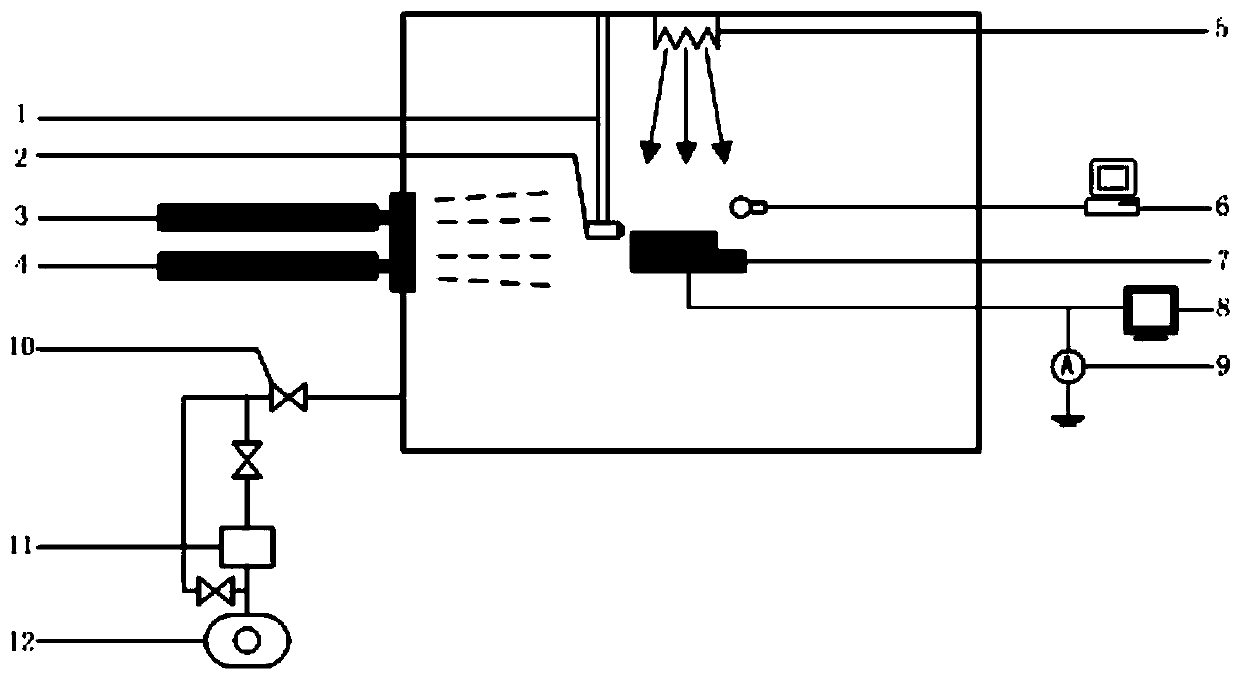
Geosynchronous orbit material non-equivalent charged test device
A technology of geosynchronous orbit and test device, applied in the direction of measuring device, measuring electrical variables, testing dielectric strength, etc., can solve the problems of difficulty in simulating plasma characteristics of energy spectrum, affecting the distribution of potential on the surface of materials, etc., and achieving controllable direction of illumination , The light direction can be adjusted and the structure is simple.
- Summary
- Abstract
- Description
- Claims
- Application Information
AI Technical Summary
Problems solved by technology
Method used
Image

Examples
Embodiment Construction
[0029] The present invention will be described in detail below with reference to the accompanying drawings and examples.
[0030] The invention provides a geosynchronous orbit material unequal electrification test device.
[0031] Firstly, the present invention places the sample to be tested in a vacuum chamber to simulate the vacuum environment of the geosynchronous orbit, then uses the double Maxwell distribution function to simulate the distribution of the high-energy plasma in the geosynchronous orbit, and uses two electron guns to simulate the distribution of the double Maxwell distribution function. The plasma energy corresponding to the two peaks can then simulate the worst environment of geosynchronous orbit. At the same time, considering that the unequal charging effect of the material is also affected by the light, the sun simulates the ultraviolet light source to simulate the irradiation situation, so as to obtain the The charge and discharge performance of the samp...
PUM
 Abstract
Description
Claims
Application Information
 - R&D Engineer
- R&D Manager
- IP Professional
- Industry Leading Data Capabilities
- Powerful AI technology
- Patent DNA Extraction
Browse by: Latest US Patents, China's latest patents, Technical Efficacy Thesaurus, Application Domain, Technology Topic, Popular Technical Reports.
© 2024 PatSnap. All rights reserved.Legal|Privacy policy|Modern Slavery Act Transparency Statement|Sitemap|About US| Contact US: help@patsnap.com