
Continuous surface exposure ceramic 3D printing device and working method thereof

A 3D printing and surface exposure technology, applied in the direction of supply devices, ceramic molding machines, manufacturing tools, etc., can solve the problems of increasing the molding time of parts, the complexity of printing devices, affecting the quality and accuracy of printed parts, and filling the solidified area of ​​​​liquid materials, etc. , to achieve the effect of saving the time of cleaning the window box, high printing efficiency, and reducing the cost of installation

Active Publication Date: 2019-05-24
QINGDAO TECHNOLOGICAL UNIVERSITY
View PDF6 Cites 11 Cited by
  • Summary
  • Abstract
  • Description
  • Claims
  • Application Information

AI Technical Summary

Problems solved by technology

Among them, photo-curing molding technologies mainly include point-by-point scanning photo-curing and surface exposure curing, but both face the problem of printing layering, which not only affects the surface quality of molded parts, but also leads to problems such as anisotropy in molded parts
Furthermore, the printing materials of light-curing 3D printing technology are mainly liquid materials, and there is a problem that liquid materials fill the solidified area.
Especially for the surface exposure light curing technology, for printing materials with high viscosity, a scraper device must be added, which increases the molding time of the part and the complexity of the printing device, thus greatly extending the overall printing time
[0005] Therefore, the existing various ceramic 3D printing technologies still face the following challenging problems: low printing efficiency; layer-by-layer printing leads to anisotropy in the molded parts, which leads to defects such as cracks and deformation in the subsequent sintering process, which seriously affects the printed parts. quality and precision

Method used


Image

  • Continuous surface exposure ceramic 3D printing device and working method thereof
  • Continuous surface exposure ceramic 3D printing device and working method thereof
  • Continuous surface exposure ceramic 3D printing device and working method thereof

Examples


Embodiment 1

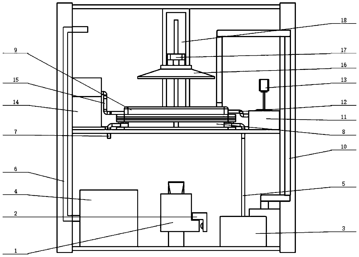
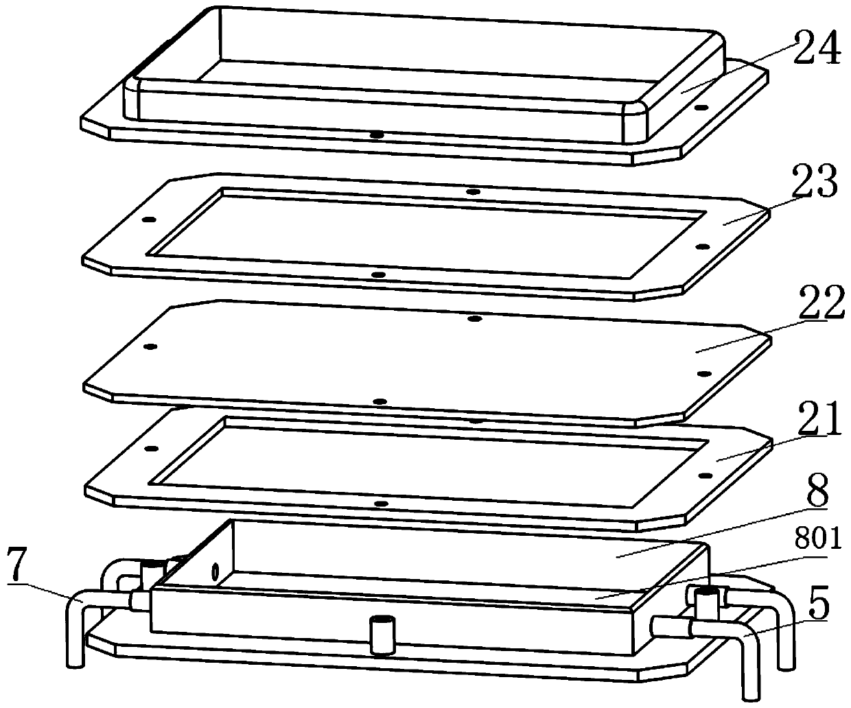
[0060] Such as figure 1 As shown, a continuous surface exposure ceramic 3D printing device includes: a chassis body, the chassis body is divided into an upper chamber and a lower chamber by a middle partition, the lower chamber is provided with an imaging module, and the upper chamber The chamber is equipped with a window box 9, a ceramic slurry circulation delivery module, an oxygen supply cooling module and a hydraulic auxiliary pressure application module, the window box and the oxygen supply cooling module are fixedly installed on the middle partition, and the oxygen supply cooling module is set Directly below the window box, the imaging device is arranged directly below the window box, a printing platform 16 is arranged directly above the window box, and the printing platform is installed on a Z-direction workbench 18. The window The box is connected to the raw material supply unit 10; the window box is provided with a liquid storage tank 24;

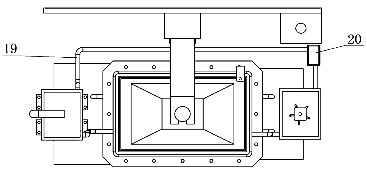
[0061] Such as figure 2 ...

Embodiment 2

[0081] Step 1: Modification of ceramic powder. First prepare a mixed solution of 5% concentration with absolute ethanol and silane coupling agent KH-570, then add alumina ceramic powder with an average particle size of 3 μm to the mixed solution at a volume ratio of 5:1. Magnetic stirring at a temperature of 8 h, filtered and dried to obtain surface-modified alumina ceramic powder;

[0082] Step 2: Configure ceramic slurry. The free radical photosensitive premix solution and PAA were used as raw materials to prepare an organic mixture solution, and the mixture was used as a solvent, and the surface-modified alumina ceramic powder (adding ratio of 4o%) produced by the above process was added in batches to it, and at the same time, the Stir at high speed (2200r / min) for 8h until the powder is evenly dispersed, then stir at low speed (500r / min) to remove foam for 2h. The free radical type resin-based alumina ceramic slurry can be obtained, and finally added to the raw material ...

Embodiment 3

[0088] Step 1: Modification of ceramic powder. First prepare a mixed solution with a concentration of 5% with absolute ethanol and silane coupling agent KH-570, then add zirconia ceramic powder with an average particle size of 20 μm to the mixed solution at a volume ratio of 4:1, at 48 ° C Stir magnetically for 9 hours at a temperature above 100°F, filter and dry to obtain surface-modified zirconia ceramic powder;

[0089] Step 2: Configure ceramic slurry. The radical photosensitive premix solution and PAA were used as raw materials to prepare an organic mixture solution, and the mixture was used as a solvent, and the surface-modified zirconia ceramic powder (addition ratio: 5o%) produced by the above-mentioned process was added in small amounts in batches, and the auxiliary Stir at high speed (2300r / min) for 9h until the powder is evenly dispersed, then stir at low speed (500r / min) to remove foam for 2h. The free radical type resin-based zirconia ceramic slurry can be obtai...


PUM

PropertyMeasurementUnit
Apertureaaaaaaaaaa
Thicknessaaaaaaaaaa
Thicknessaaaaaaaaaa

Abstract

The invention discloses a continuous surface exposure ceramic 3D printing device and a working method thereof. Before printing, a raw material feeding unit pours ceramic slurry into a window box; after a water pump pulls out the ceramic slurry in a first slurry tank, the ceramic slurry is conveyed into a second slurry tank through a second slurry conveying pipeline, the ceramic slurry in the second slurry tank flows into aliquidstorage tank of the window box through the second slurry conveying pipeline, the ceramic slurry in the liquid storage tank of the window box flows into the first slurrytank through the first slurry conveying pipeline, and the circulation flow of ceramic slurry in the first slurry tank, the liquid storage tank, and the second slurry tank is realized throughthe waterpump; and the continuous surface exposure technology is adopted, continuous molding of ceramic 3D printing is realized, and continuous printing is realized.

Description

technical field [0001] The present disclosure relates to a continuous surface exposure ceramic 3D printing device and a working method thereof. Background technique [0002] The statements in this section merely mention background art related to the present disclosure and do not necessarily constitute prior art. [0003] Ceramic materials have outstanding advantages such as high strength, high hardness, high temperature resistance, oxidation resistance, corrosion resistance, stable chemical properties, and light weight (low density). Wide range of applications. However, the traditional ceramic forming technology faces the disadvantages and limitations of processing difficulties (especially complex aggregate shape structures), long manufacturing cycle, and high production cost, which restrict the wider application of ceramic parts. Compared with the traditional ceramic molding process, ceramic 3D printing technology has the following significant advantages: (1) No need for ...

Claims


Application Information

Patent Timeline
IPC IPC(8): B28B1/00B28B13/02B33Y10/00B33Y30/00C04B35/10C04B35/48C04B35/505C04B35/584C04B35/04C04B35/622
Inventor 张广明蒋进兰红波王赫王智
Owner QINGDAO TECHNOLOGICAL UNIVERSITY
Learn More