Electrical connector and conductive terminal thereof

A technology of conductive terminals and electrical connectors, applied in the direction of connection, parts of connecting devices, circuit/collector parts, etc., can solve problems such as damage to electrical connectors, achieve high corrosion resistance, and reduce short-circuit fire. effect of risk

Inactive Publication Date: 2019-05-21
FOXCONN (KUNSHAN) COMPUTER CONNECTOR CO LTD +1
View PDF3 Cites 1 Cited by
  • Summary
  • Abstract
  • Description
  • Claims
  • Application Information

AI Technical Summary

Problems solved by technology

However, when liquid or foreign matter enters the electrical connector, it is easy to short-circuit and catch fire between the adjacent contact parts of the conductive terminals and damage the electrical connector.

Method used


Image

  • Electrical connector and conductive terminal thereof
  • Electrical connector and conductive terminal thereof
  • Electrical connector and conductive terminal thereof

Examples


Embodiment Construction

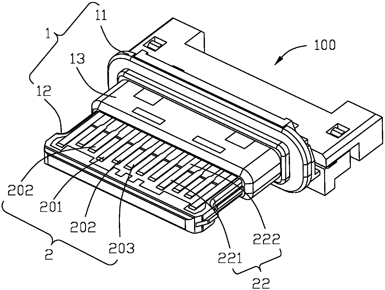
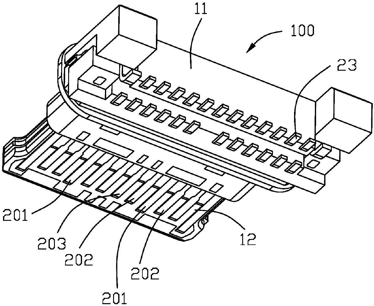
[0022] Please refer to Figure 1 to Figure 5 As shown, the electrical connector 100 of the present invention is a connector for being installed on a circuit board (not shown) and can be plugged in both front and back. The electrical connector 100 includes an insulating body 1 , and conductive terminals 2 arranged in two rows above and below the insulating body 1 .

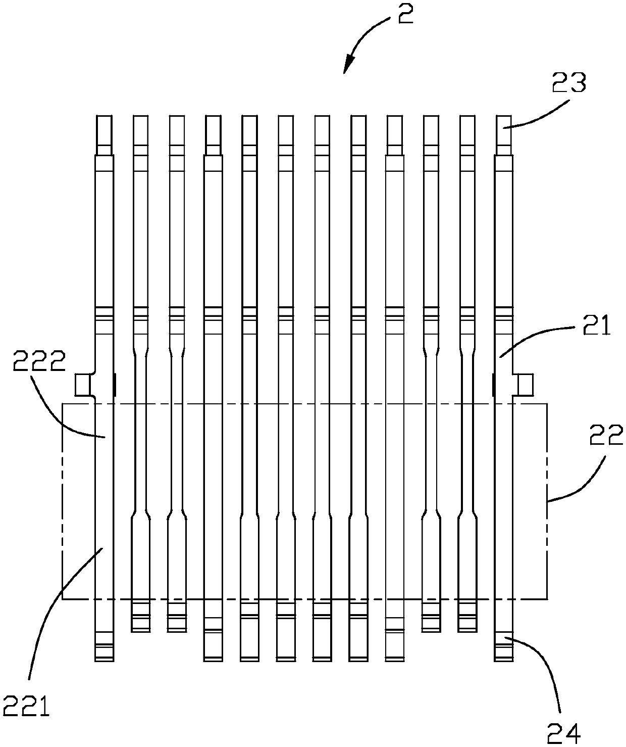
[0023] refer to Figure 1 to Figure 3 As shown, the insulating body 1 includes a base portion 11 and a tongue portion 12 extending forward from the base portion 11 . The conductive terminal 2 includes a holding portion 21 held on the base portion 11, a contact portion 22 extending forward from the holding portion 21 and exposed to the tongue portion 12, and a contact portion 22 extending backward from the holding portion. The welding part 23 of the base part 11 . The tongue portion 12 includes two surfaces facing up and down, and the two rows of conductive terminals 2 are respectively arranged on the two surface...


PUM


Abstract

An electrical connector comprises an insulation body and at least one row of conductive terminals, wherein the at least one row of conductive terminals is accommodated in the insulation body, the insulation body comprises a base part and a tongue plate part, the tongue plate part forwards extends from the base part, each conductive terminal comprises a clamping and fixing part, a contact part anda welding part, the clamping and fixing part is clamped and fixed at the base part, the contact part is formed by forward extending from the clamping and fixing part and is exposed out of the tongue plate, the welding part backwards extends out of the base part from the clamping and fixing part, the contact part is provided with a contact region and a non-contact region, the contact region is in contact with an abutting terminal of an abutting connector, the non-contact region is not in contact with the abutting terminal, and an electrophoresis layer is arranged on a surface of the non-contactregion and is not arranged on a surface of the contact region. The electrophoresis is not arranged at the contact region of the contact part of the conductive terminal while is arranged at the non-contact region, the electrophoresis layer has relatively high corrosion resistance, and the risk of short-connected fire between the contact parts of adjacent conductive terminals can be effectively reduced.

Description

【Technical field】 [0001] The invention relates to an electric connector and its conductive terminal, in particular to an electric connector which can be inserted in the forward and reverse directions. 【Background technique】 [0002] China Patent Application No. CN105449438A discloses an electrical connector, which includes an insulating body, a number of conductive terminals disposed on the insulating body, and a shielding shell covering the insulating body. The insulating body includes a base and a a tongue portion extending forward from the base, the conductive terminal includes a holding portion held on the base, a welding portion extending backward from the holding portion out of the base, and extending forward from the holding portion out of the contact portion exposed to the surface of the tongue portion. However, when liquid or foreign matter enters the electrical connector, adjacent contact portions of the conductive terminals are easily short-circuited to cause fir...

Claims


Application Information

Patent Timeline
IPC IPC(8): H01R13/03
CPCC25D13/02C25D13/12C25D13/22H01R13/03H01R43/16C25D7/06H01R13/405H01R43/00
Inventor 赵俊
Owner FOXCONN (KUNSHAN) COMPUTER CONNECTOR CO LTD
Why Eureka
Try Eureka