
Method for in-situ circularly promoting catalytic performance of NiP amorphous alloy

A technology of amorphous alloy and catalytic performance, which is applied in chemical instruments and methods, catalyst activation/preparation, physical/chemical process catalysts, etc. It can solve the problems of electrolyzed water and high hydrogen evolution overpotential, and achieve surface roughness increase and hydrogen evolution The effect of performance improvement and simple method

Inactive Publication Date: 2019-05-10
NANJING UNIV OF SCI & TECH
View PDF6 Cites 5 Cited by
  • Summary
  • Abstract
  • Description
  • Claims
  • Application Information

AI Technical Summary

Problems solved by technology

Although stainless steel electrodes and nickel mesh electrodes are relatively low in price, rich in reserves, and not easily corroded in alkaline solutions, their hydrogen evolution overpotentials are relatively high under high current density electrolysis conditions, which has become an important issue that plagues the development of the electrolyzed water industry. reason

Method used


Image

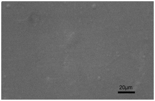
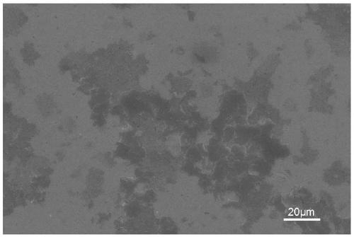
  • Method for in-situ circularly promoting catalytic performance of NiP amorphous alloy
  • Method for in-situ circularly promoting catalytic performance of NiP amorphous alloy
  • Method for in-situ circularly promoting catalytic performance of NiP amorphous alloy

Examples


Embodiment 1

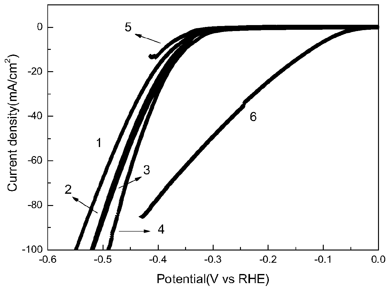
[0023] Embodiment 1, comprises the following steps:

[0024] Step 1), using pure nickel (99.99%) and red phosphorus (99.999%) as raw materials, according to NiP 22 The atomic percentage is configured with a master alloy, and the master alloy is first induction-melted into an alloy ingot in a melting and quenching strip machine;

[0025] Step 2), put the alloy ingot into the vacuum arc melting furnace for further melting, so that the composition is more uniform, which is beneficial to the subsequent stripping;

[0026] In step 3), the alloy ingot melted by vacuum arc is prepared by strip throwing method to prepare amorphous thin strips, wherein, in order to suppress the process of crystal nucleation and growth of crystal nuclei, the cooling rate is controlled by 10 4 K / s~10 6 K / s;

[0027] Step 4), using 1M KOH as the electrolyte, connecting the amorphous strip to a copper wire as a working electrode, a graphite electrode as a counter electrode, and a Hg / HgO / 1M KOH electrode...

Embodiment 2

[0028] Embodiment 2, comprises the steps:

[0029] Step 1)-step 3) repeat embodiment 1;

[0030] Step 4), using 1M KOH as the electrolyte, connecting the amorphous strip to a copper wire as a working electrode, a graphite electrode as a counter electrode, and a Hg / HgO / 1M KOH electrode as a reference electrode. With a scanning speed of 500mV / s, in the voltage range of -0.4V~-2V, scan the cyclic voltammetry curve 10,000 times, and then measure the polarization curve at 5mV / s.

Embodiment 3

[0031] Embodiment 3, comprises the following steps:

[0032] Step 1)-step 3) repeat embodiment 1;

[0033] Step 4), using 1M KOH as the electrolyte, connecting the amorphous strip to a copper wire as a working electrode, a graphite electrode as a counter electrode, and a Hg / HgO / 1M KOH electrode as a reference electrode. With a scanning speed of 500mV / s, in the voltage range of -0.4V~-2V, scan the cyclic voltammetry curve 20,000 times, and then measure the polarization curve at 5mV / s.


PUM

PropertyMeasurementUnit
areaaaaaaaaaaa

Abstract

The invention discloses a method for in-situ circularly promoting a catalytic performance of a NiP amorphous alloy. Expression formula of the NiP amorphous alloy is NiP20-22. The method comprises thefollowing steps: taking 1M KOH as an electrolyte; connecting a NiP amorphous alloy thin strip with a copper wire and then using as a working electrode; taking a graphite electrode as a counter electrode; taking a Hg / HgO / 1M KOH electrode as a reference electrode; performing cyclic voltammetry scanning for more than 5000 times within a voltage range from -0.4V to -2V. According to the invention, repeated cyclic voltammetry scanning is performed in the electrolyte, so that the surface roughness of the NiP amorphous alloy thin strip is increased and the hydrogen evolution performance of the NiP amorphous alloy thin strip is promoted; the method is simple; pollution caused by P volatilization is reduced and hydrogen evolution performance of material is effectively promoted.

Description

technical field [0001] The invention belongs to the research of electrolytic water hydrogen evolution materials, in particular to a method for improving the catalytic performance of NiP amorphous alloy by in-situ circulation. Background technique [0002] Due to the continuous consumption of fossil fuels and the increasingly prominent environmental problems, the search for clean and sustainable new energy has attracted more and more attention. Among many new energy sources, hydrogen energy has become a hot spot in new energy research due to its advantages of high energy density, cleanness (the product is water) and sustainable utilization. Hydrogen production by electrolysis of water is a highly efficient and applicable method. [0003] In the earliest electrolytic water electrode materials, noble metal Pt and Pd were mainly used as electrode materials, because they were not easy to be oxidized, hydrogen evolution and oxygen evolution overpotentials were relatively low, and...

Claims


Application Information

Patent Timeline
Patent Type & Authority Applications(China)
IPC IPC(8): B01J27/185B01J35/10B01J37/34C25F3/02C25B1/04C25B11/06
Inventor 冯涛陈菲陈双琴
Owner NANJING UNIV OF SCI & TECH
Learn More