Production method for composite insulation pipe

A technology of composite heat preservation and production method, which is applied in the field of composite pipes, can solve problems such as slipping of outer pipes, easy damage of composite pipes, shrinkage of inner pipes, etc., and achieve the effects of prolonging service life, preventing pipe bursting, and not being easy to fall off and damage

Inactive Publication Date: 2019-04-05
GUANGZHOU LIYANG ENERGY TECH CO LTD
View PDF3 Cites 1 Cited by
  • Summary
  • Abstract
  • Description
  • Claims
  • Application Information

AI Technical Summary

Problems solved by technology

[0002] The existing composite pipes have poor strength resistance, are easily deformed and damaged after applying pressure, and cannot be restored to their original shape, which affects the normal use of the composite pipe, and there is no fixed positioning structure between the inner and outer pipes. As a result, the inner pipe is easy to slip, resulting in different local mechanical strengths of the pipe, which makes the composite pipe easy to be damaged; on the other hand, due to the alternation of cold and heat, the inner pipe may shrink and slip from the outer pipe.
[0003] There are various types of composite tubes. Among them, the thermal insulation tube has no antibacterial properties and will accumulate a large number of bacteria after long-term use. The nano-silver composite tube is a plastic composite tube composed of nano-silver coating, PPR tube and PEF tube. The nano-silver coating and The antibacterial agent is formed on the surface of the PPR tube. Since the PPR tube is not porous, the nano-silver coating on its surface will affect its antibacterial function, and the strength of the plastic composite tube is far inferior to that of the stainless steel tube. Afterwards, it is easy to be deformed and damaged, and has the defects of short life and poor heat preservation effect

Method used


Image

  • Production method for composite insulation pipe

Examples


Embodiment example 1

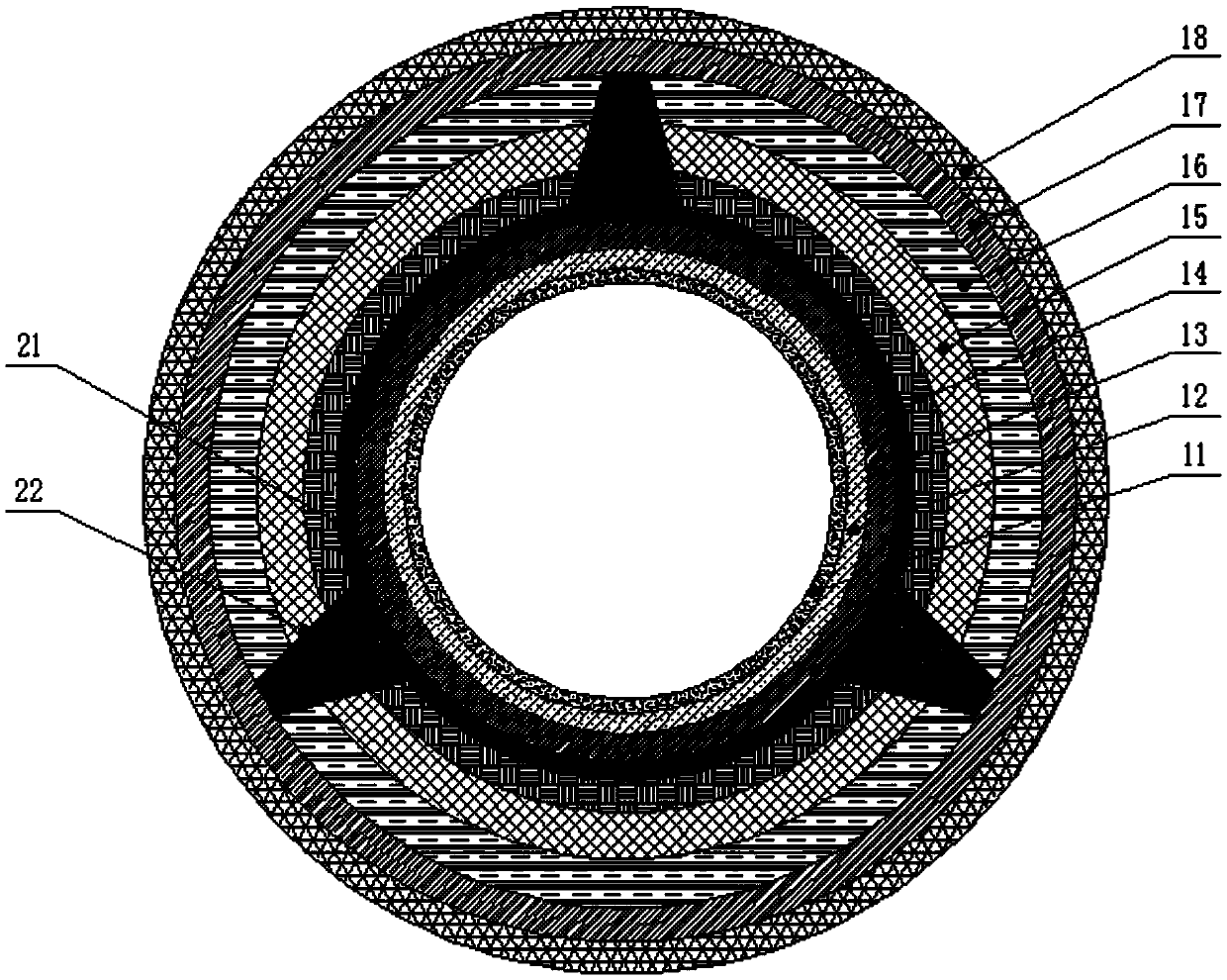
[0031] according to figure 1 As shown, a heat preservation pipe includes nano-silver coating 11, porous silica gel pipe 12, stainless steel pipe 13, high temperature resistant fiber felt 14, sodium silicate heat preservation pipe 15, polyurethane foam layer 16, carbon steel pipe from outside to inside 17 and three layers of PE coating 18, a positioning ring 21 is arranged between the carbon steel pipe and the stainless steel pipe, and the outer wall of the positioning ring extends outward to form several positioning bosses 22, and the positioning ring is fixedly sleeved on the The outer wall of the stainless steel pipe, the outer wall of the positioning boss is fixed on the inner wall of the carbon steel pipe.

[0032] The stainless steel pipe includes the following components by weight: 700-900 parts of steel scrap, 20-40 parts of ferroboron, 0.5-2 parts of carbon, 5-10 parts of silicon, 5-10 parts of manganese, 150-200 parts of chromium, nickel 60-100 parts and sulfur 0.1-0...

Embodiment example 2

[0034] A method for producing a composite insulation pipe, comprising the following steps:

[0035] S1: Preparation of stainless steel pipe: put the following components by weight into a melting furnace for melting: 700 parts of steel scrap, 20 parts of ferroboron, 0.5 parts of carbon, 5 parts of silicon, 5 parts of manganese, 150 parts of chromium, 60 parts of nickel and sulfur 0.1 part; after the molten steel is melted, a small amount of aluminum is added for deoxidation, and the slag is removed from the furnace at 1560°C; after the furnace is left to stand and naturally cooled for 150s, the centrifugal casting of stainless steel pipes is carried out; the centrifugal casting condition is that the line speed of the centrifuge is 30m / s, pouring thickness is 5mm;

[0036] S2: Preparation of composite tube A: Spray nano-silver coating on one side of the porous silica gel sheet to form a coating, and then roll it into a tube shape;

[0037] S3: Preparation of the composite pipe ...

Embodiment example 3

[0045] A method for producing a composite insulation pipe, comprising the following steps:

[0046] S1: Preparation of stainless steel pipe: put the following components by weight into a melting furnace for melting: 900 parts of steel scrap, 40 parts of ferroboron, 2 parts of carbon, 10 parts of silicon, 10 parts of manganese, 200 parts of chromium, 100 parts of nickel and sulfur 0.5 parts; after the molten steel is melted, a small amount of aluminum is added for deoxidation, and the slag is removed from the furnace at 1600°C; after the furnace is left to stand, and after natural cooling for 200s, the centrifugal casting of stainless steel pipes is carried out; the centrifugal casting condition is centrifuge line speed 40m / s, pouring thickness is 10mm;

[0047] S2: Preparation of composite tube A: Spray nano-silver coating on one side of the porous silica gel sheet to form a coating, and then roll it into a tube shape;

[0048] S3: Preparation of the composite pipe B: the out...


PUM

PropertyMeasurementUnit
thicknessaaaaaaaaaa
thicknessaaaaaaaaaa
thicknessaaaaaaaaaa

Abstract

The invention belongs to the field of composite pipe. An insulation pipe sequentially comprises a nanometer silver coating layer, a porous silicone tube, a stainless steel pipe, a high temperature resistance fiber felt, a sodium silicate insulation pipe, a polyurethane foaming layer, a carbon steel layer and three PE coating layers from outside to inside; a positioning ring is arranged between thecarbon steel layer and the stainless steel pipe; the outer wall of the positioning ring extends outwards to be formed with a plurality of positioning bosses; the positioning ring is fixedly connectedto the outer wall of the stainless steel pipe in a sleeving manner; and the outer walls of the positioning bosses are fixed to the inner wall of the carbon steel layer. A production method comprisesthe following steps of stainless steel pipe preparation, composite pipe A preparation, composite pipe B preparation, composite pipe C preparation, composite pipe D preparation, composite pipe E preparation, composite pipe F preparation, composite pipe G preparation and insulation pipe preparation. The prepared insulation pipe has the advantages of strong antibacterial property, strong impact resistance, good high temperature resistance, good insulation performance, difficulty in deformation damage, long service life and the like, can be rebounded to an original state after deformation with heating and does not influence normal use of a product.

Description

technical field [0001] The invention relates to the field of composite pipes, in particular to a production method of composite heat preservation pipes. Background technique [0002] The existing composite pipes have poor strength resistance, are easily deformed and damaged after applying pressure, and cannot be restored to their original shape, which affects the normal use of the composite pipe, and there is no fixed positioning structure between the inner and outer pipes. As a result, the inner pipe is easy to slip, resulting in different local mechanical strengths of the pipe, making the composite pipe easy to damage; on the other hand, due to the alternation of cold and heat, the inner pipe may shrink in diameter, and then slip off from the outer pipe. [0003] There are various types of composite tubes. Among them, the thermal insulation tube has no antibacterial properties and will accumulate a large number of bacteria after long-term use. The nano-silver composite tub...

Claims


Application Information

Patent Timeline
Patent Type & Authority Applications(China)
IPC IPC(8): B29D23/00B22D13/02C22C38/54C22C38/02C22C38/04
CPCB22D13/02B29D23/001C22C38/02C22C38/04C22C38/54
Inventor 陈美红汤荣华唐志军汤问天方可安唐国良冯铁军陈任军张圆明黄阔
Owner GUANGZHOU LIYANG ENERGY TECH CO LTD
Why Eureka
Try Eureka