Biomass combustor

A burner and biomass technology, applied in the combustion method, combustion equipment, combustion of solid fuel, etc., can solve the problems of small combustion area, small firepower, difficulty in ignition, etc., to increase the combustion area, save manufacturing costs, and have a simple structure Effect

Pending Publication Date: 2019-03-08
宜昌益烟机械设备有限公司
View PDF1 Cites 1 Cited by
  • Summary
  • Abstract
  • Description
  • Claims
  • Application Information

AI Technical Summary

Problems solved by technology

As a dual-purpose biomass burner described in Chinese patent document CN 207486837 U, the size of the combustion pool, that is, the combustion head, is fixed. In addition, when the wind from the blower enters the combustion head, the direction of the wind will blow forward. The direction of the flame does not guarantee complete upward combustion; the ignition device in this document is one, and there is no air passage, which makes it difficult to ignite the biomass fuel at the initial ignition
[0003] In actual production, the size and structure of the combustion head is set for the furnace mouth of the tea oven. Due to the certain size of the furnace mouth, the size and structure of the combustion head of the existing biomass burner is fixed. One of the biggest disadvantages of this structure is : The combustion area is small, the firepower is small, and the biomass fuel is not fully burned, which cannot meet the needs of the existing tea oven; secondly, when the combustion head of the existing biomass burner is in use, the flame will burn forward under the action of the blower , rather than burning upwards, but it has been proved in practice that the flames burning upwards are the best
[0004] Therefore, a biomass combustion device with higher combustion efficiency and firepower requirements is very promising in the market, but there is no such device at present.

Method used


Image

  • Biomass combustor
  • Biomass combustor
  • Biomass combustor

Examples


Embodiment Construction

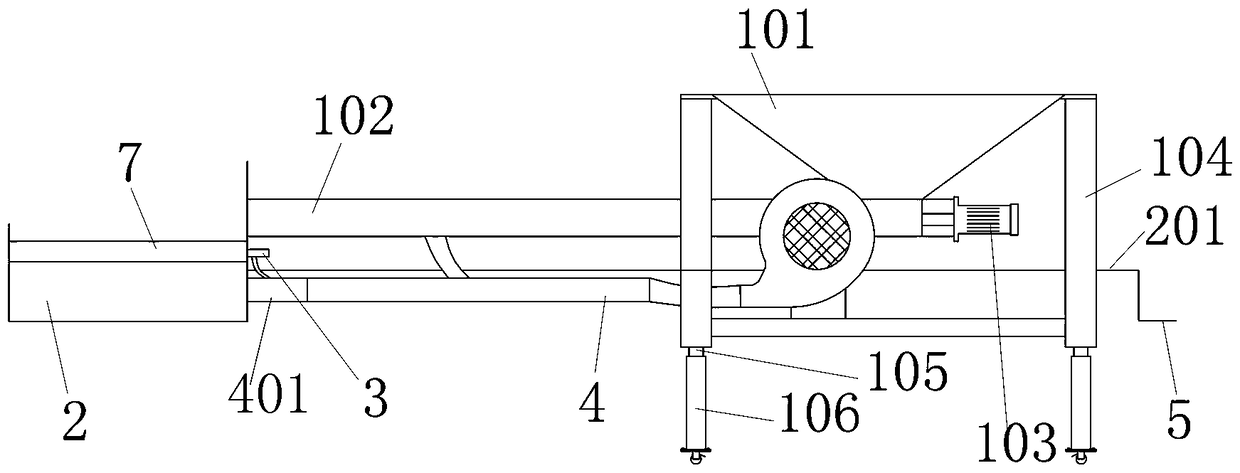
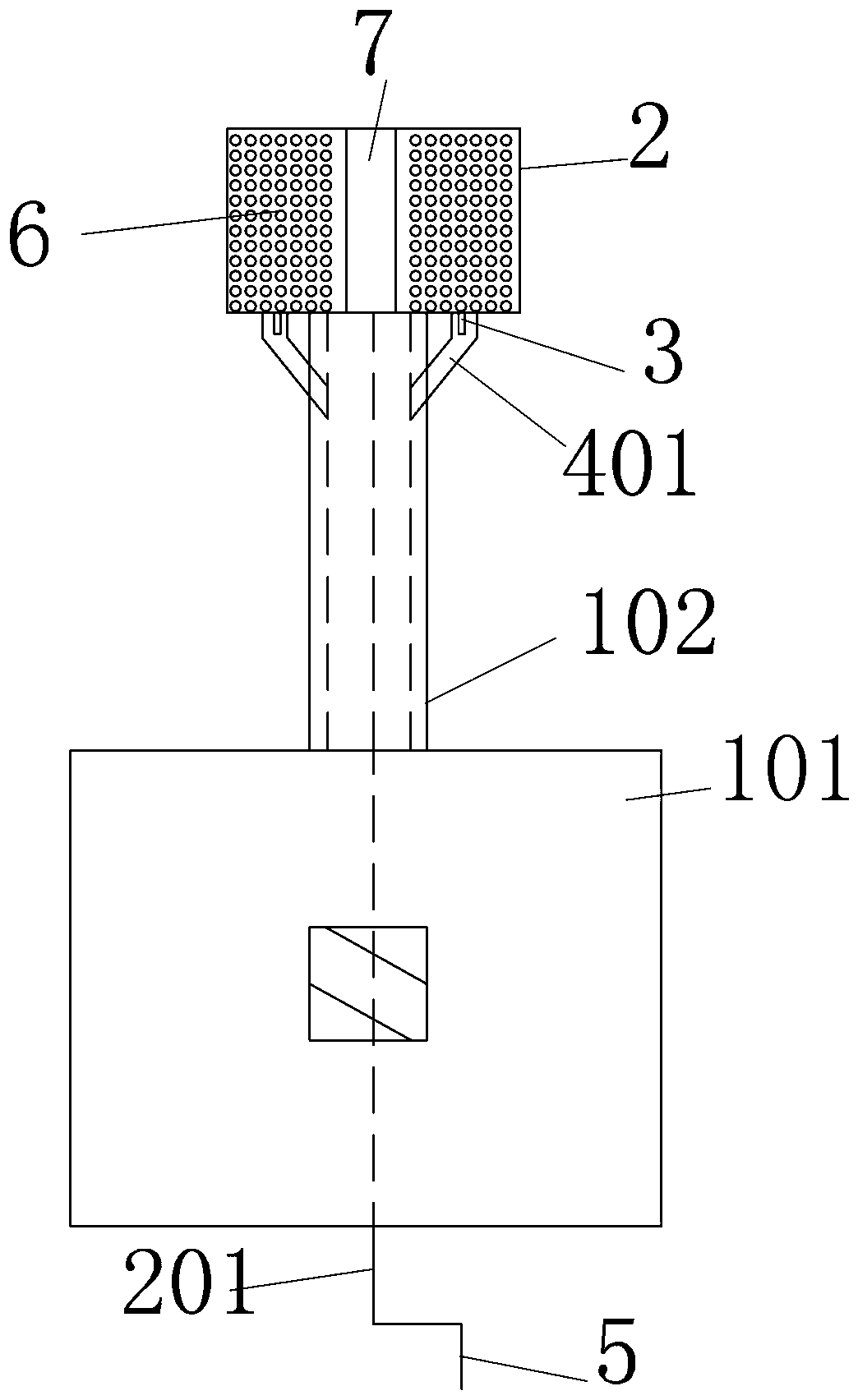
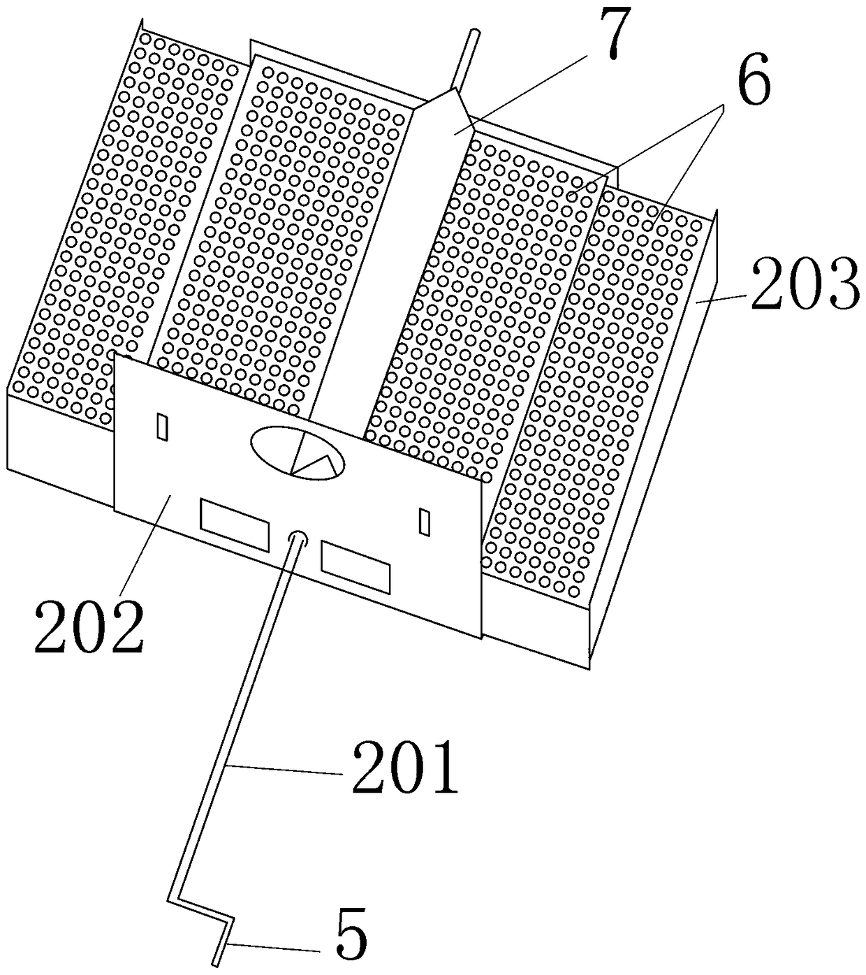
[0042] The preferred solution is as Figure 1 to Figure 4 As shown, a biomass burner includes a feeding device, the feeding device is supported by a bracket 104, the feeding device includes a hopper 101, the bottom of the hopper 101 is provided with a feeding pipe 102, and a feeding device is arranged inside the feeding pipe. Power mechanism is the feeder 103 that is installed in feed pipe 102 afterbody, and feed pipe 102 head is provided with telescopic combustion head 2, and telescopic combustion head 2 is covered with a plurality of pieces of breathable mesh 6, and the retractable combustion head 2 Be provided with a plurality of ignition device sleeve pipes 3 next to the feed inlet, and below the ignition device sleeve pipes 3 are provided with air supply branch pipes 401 of a plurality of air supply pipes 4, the air supply branch pipes 401 communicate with the ignition device sleeve pipes 3, and the air supply pipes 4 It communicates with the feed pipe 102; the rotating s...


PUM


Abstract

The invention provides a biomass combustor which comprises a feeding device. The feeding device is supported through a support. The feeding device comprises a hopper. The bottom of the hopper is provided with a feeding pipe. The feeding device is arranged in the feeding pipe. A power mechanism of the feeding device is a feeding machine installed on the tail portion of the feeding pipe. The head ofthe feeding pipe is provided with a telescoping type combustion head. The telescoping type combustion head is covered with multiple ventilating nets. Multiple ignition device sleeve pipes are arranged beside a feeding opening of the telescoping type combustion head. Wind supply branch pipes of multiple wind supply pipes are arranged below the ignition device sleeve pipes. The wind supply branch pipes communicate with the ignition device sleeve pipes. The wind supply pipes communicate with the feeding pipe. A rotating shaft of the telescoping type combustion head is connected with the power device. According to the device, under the circumstance of ensuring that the telescoping type combustion head can come into and out of a furnace opening freely, the size of the combustion area of the telescoping type combustion head can be changed, combustion fullness of biomass fuel is improved, and the flames are enhanced. In addition, the device can ensure that the flames are upward and high in heat efficiency.

Description

technical field [0001] The invention belongs to the field of biomass burning devices, in particular to a biomass burning machine. Background technique [0002] At present, biomass fuel is an environmentally friendly fuel, which produces less dust, less smoke, and high combustion value during the combustion process. It has been widely used in industrial production processes, and biomass burners are widely used in tea drying. In the field of roasting, the size of the combustion head of the existing biomass burner is fixed and when the biomass fuel is burning, the direction of the flame is not vertically upward. As a dual-purpose biomass burner described in Chinese patent document CN 207486837 U, the size of the combustion pool, that is, the combustion head, is fixed. In addition, when the wind from the blower enters the combustion head, the direction of the wind will blow forward. The direction of the flame cannot guarantee complete upward combustion; the ignition device in t...

Claims


Application Information

Patent Timeline
IPC IPC(8): F23B30/02F23B40/00F23H11/00F23H11/20F23L5/02
CPCF23B30/02F23B40/00F23H11/00F23H11/20F23L5/02
Inventor 张廷茂蔡偶超刘爱辉钱祖坤高宁刘兴鑫张廷艳王明华宋小飞胡晓娟何克俊向桦枫陈琼莉陈美伶张先星
Owner 宜昌益烟机械设备有限公司
Why Eureka
Try Eureka