Method for controlling close limit hardness of steel used for compressor shell
A technology of hardness control and compressor, which is applied in the field of metal rolling, can solve the problems of no demoulding, unsystematic introduction of surface hardness control measures for hot-rolled pickling low-carbon steel, and high hardness of steel coils, so as to eliminate the impact , Inhibit the migration of elements and reduce the effect of secondary cementite precipitation at the grain boundary
- Summary
- Abstract
- Description
- Claims
- Application Information
AI Technical Summary
Problems solved by technology
Method used
Image

Examples
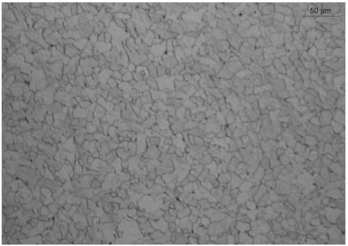
Embodiment 1
[0036] The steel used for the compressor casing in this embodiment is SPHC finished steel with a thickness of 3.0mm, and its chemical composition and mass percentage are: C: 0.023%, Si: 0.06%, Mn: 0.21%, P: 0.011%, S: 0.007%, Als: 0.026%, the rest is Fe and unavoidable impurities.
[0037] The production method of the steel SPHC for the compressor shell of this embodiment includes casting slab heating, controlled rolling, controlled cooling, and coiling processes, and the specific process steps are as follows:
[0038] (1) Slab heating process: the heating temperature of the slab is 1190°C, and the heating time is 210 minutes;
[0039] (2) Controlled rolling process: rough rolling passes 3+3, intermediate billet thickness 42mm, finish rolling entrance temperature 995°C, finish rolling temperature 879°C;
[0040] (3) Control the cooling process: laminar flow cooling is adopted, the cooling model adopts the centralized cooling mode in the front section, and the cooling rate is ...
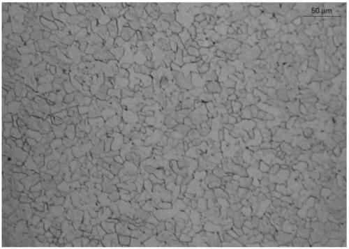
Embodiment 2
[0044] The steel used for the compressor casing in this embodiment is SPHC finished steel with a thickness of 3.5mm, and its chemical composition and mass percentage are: C: 0.023%, Si: 0.06%, Mn: 0.21%, P: 0.011%, S: 0.007%, Als: 0.026%, the rest is Fe and unavoidable impurities.
[0045] The production method of the steel SPHC for the compressor shell of this embodiment includes casting slab heating, controlled rolling, controlled cooling, and coiling processes, and the specific process steps are as follows:
[0046] (1) Slab heating process: the heating temperature of the slab is 1192°C, and the heating time is 215 minutes;
[0047] (2) Controlled rolling process: 3+3 rough rolling passes, intermediate billet thickness 42mm, finish rolling entrance temperature 998°C, final rolling temperature 882°C;
[0048] (3) Control the cooling process: laminar flow cooling is adopted, and the cooling model adopts the centralized cooling mode in the front section, and the cooling rate ...
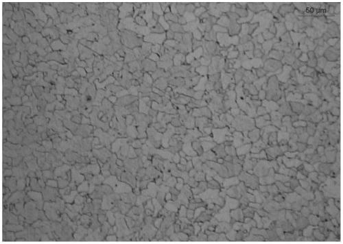
Embodiment 3
[0052] The steel used for the compressor casing in this embodiment is SPHC finished steel with a thickness of 3.0mm, and its chemical composition and mass percentage are: C: 0.023%, Si: 0.06%, Mn: 0.21%, P: 0.011%, S: 0.007%, Als: 0.026%, the rest is Fe and unavoidable impurities.
[0053]The production method of the steel SPHC for the compressor shell of this embodiment includes casting slab heating, controlled rolling, controlled cooling, and coiling processes, and the specific process steps are as follows:
[0054] (1) Slab heating process: the heating temperature of the slab is 1196°C, and the heating time is 206 minutes;
[0055] (2) Controlled rolling process: rough rolling passes 3+3, intermediate billet thickness 42mm, finish rolling entrance temperature 1005°C, finish rolling temperature 876°C;
[0056] (3) Control the cooling process: laminar flow cooling is adopted, the cooling model adopts the centralized cooling mode in the front section, and the cooling rate is ...
PUM
| Property | Measurement | Unit |
|---|---|---|
| Thickness | aaaaa | aaaaa |
| Thickness | aaaaa | aaaaa |
Abstract
Description
Claims
Application Information
 - R&D
- Intellectual Property
- Life Sciences
- Materials
- Tech Scout
- Unparalleled Data Quality
- Higher Quality Content
- 60% Fewer Hallucinations
Browse by: Latest US Patents, China's latest patents, Technical Efficacy Thesaurus, Application Domain, Technology Topic, Popular Technical Reports.
© 2025 PatSnap. All rights reserved.Legal|Privacy policy|Modern Slavery Act Transparency Statement|Sitemap|About US| Contact US: help@patsnap.com