


Quick Research
Generate reliable direction feasibility study reports for your R&D in just a few steps.

Technical Q&A
Discover and master advanced knowledge NOW. Basics, ideas, possibilities, all at once.

Find Solutions
As an expert in R&D theories, this can generate solutions to your technical problems instantly.

Evaluate Feasibility
Analyze your overall solution with one click, know your potential R&D risks in advance.

Monitor Landscape
Get weekly tech updates, stay abreast of the latest tech innovations and key insights.
Battery recovery detection device of new energy automobile
A new energy vehicle and battery recycling technology, applied in the direction of measuring devices, measuring electricity, conductive coatings, etc., can solve the problems of reducing the service life of the device, fixing troubles, and the battery is prone to static electricity, etc., to achieve the effect of preventing static electricity and convenient fixing
- Summary
- Abstract
- Description
- Claims
- Application Information
AI Technical Summary
Problems solved by technology
Method used
Image

Examples
Embodiment 1
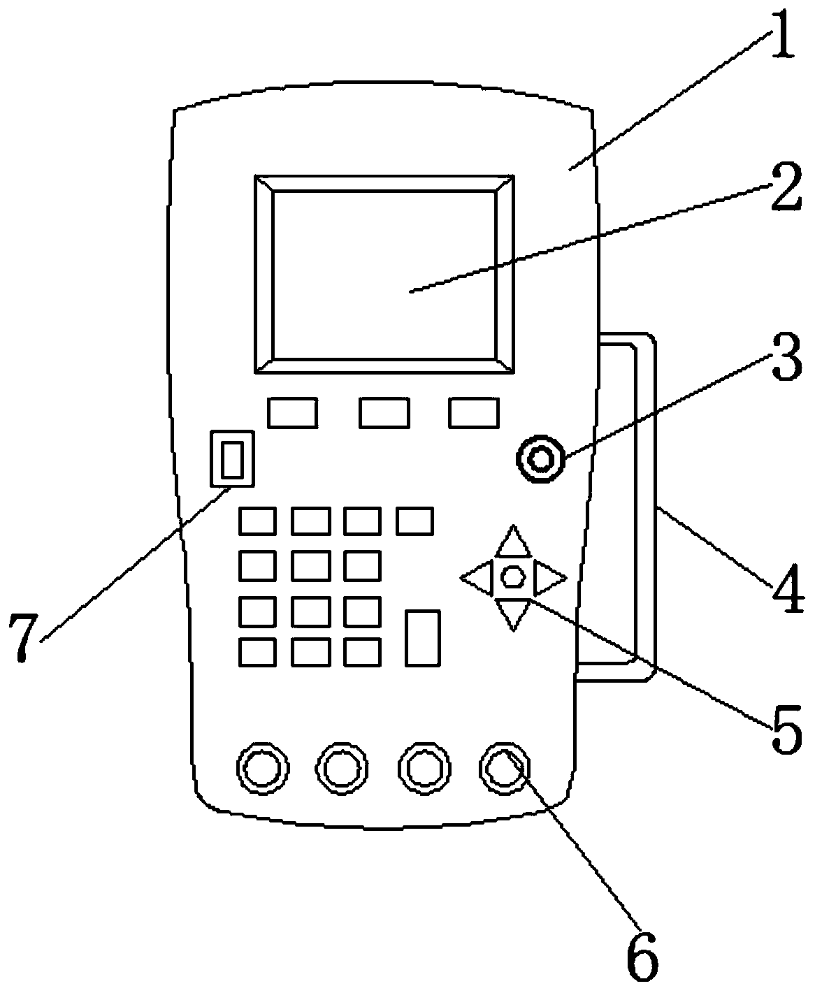
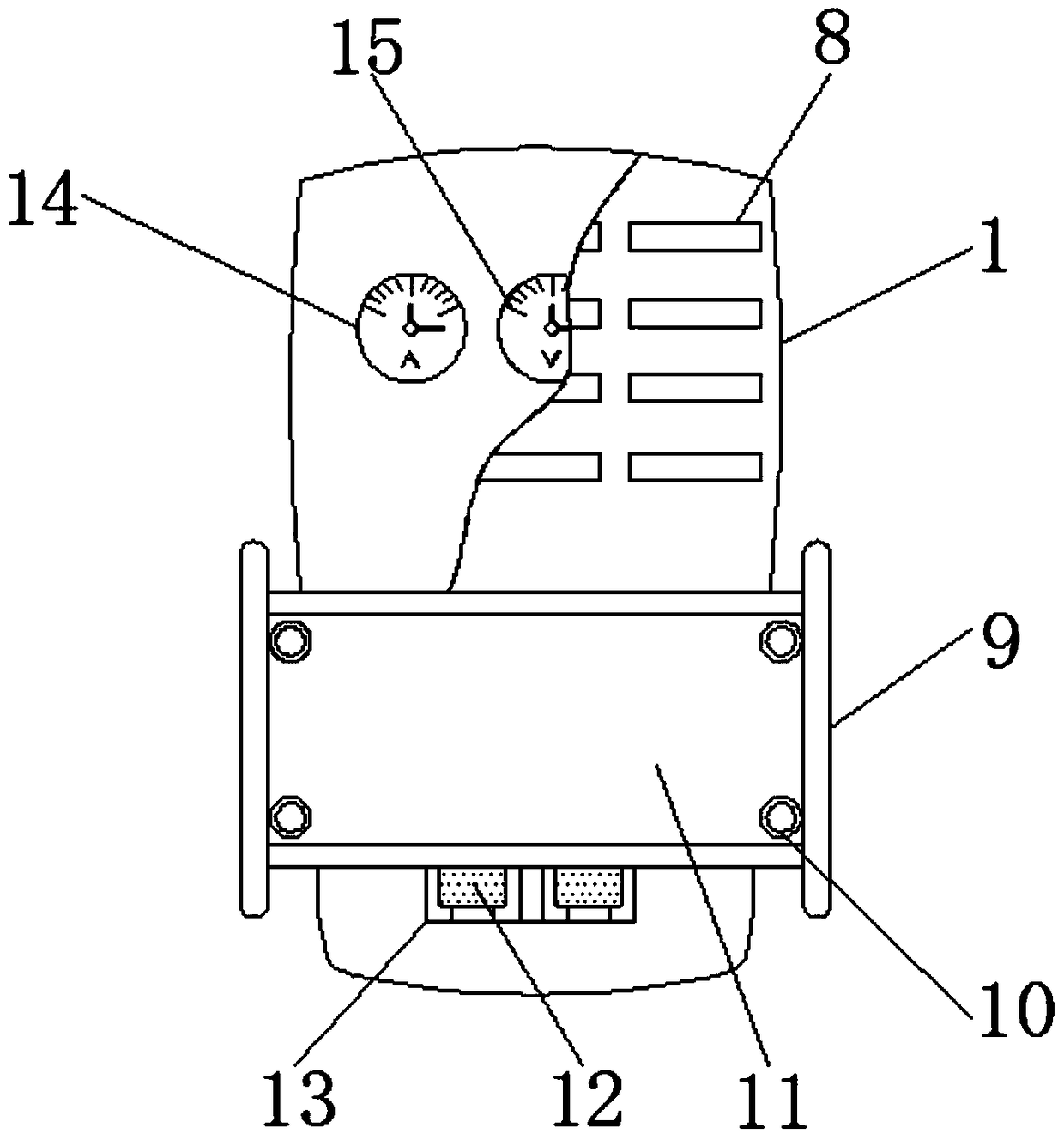
[0026] see Figure 1-3 , the present invention provides a technical solution: a new energy vehicle battery recycling detection device, including a detector body 1, a display screen 2 is arranged above the front surface of the detector body 1, and the display screen 2 is fixedly connected to the detector body 1, The right side of the detector body 1 is provided with a handle 4, and the handle 4 is fixedly connected to the detector body 1, and the right side of the front surface of the detector body 1 is provided with an alarm indicator light 3 near the lower right side of the display screen 2, and the alarm indicator light 3 It is fixedly connected with the detector body 1, a power switch 7 is arranged on the left side of the front surface of the detector body 1 near the lower left side of the display screen 2, and the power switch 7 is fixedly connected with the detector body 1, and the bottom end of the detector body 1 front surface is provided with a terminal 6, and the term...
Embodiment 2
[0041] The difference from Example 1 is that the detector body 1 is coated with an antistatic layer, and the preparation method of the antistatic layer is:
[0042] Take the following raw materials of each component by weight for later use: 20 parts of water-based epoxy resin emulsion, 10 parts of diatomaceous earth, 8 parts of conductive mica powder, 17 parts of polyurethane acrylate, 5 parts of sodium alkylsulfonate, glycerol-stearic acid 4 parts of ester, 30 parts of polyethylene, 2 parts of pyridine.
[0043] S1. Prefabricated organic solvent: mix water-based epoxy resin emulsion, polyurethane acrylate, and polyethylene, heat to 52°C, stir evenly, and keep warm for 1.5h;
[0044] S2. Preparation of antistatic material: add sodium alkylsulfonate, glycerol monostearate, pyridine, conductive mica powder, and diatomaceous earth to the organic solvent in S1 in sequence, stir evenly, and heat the temperature to 63°C Post-insulation for 2h;
[0045] S3. Cleaning: Clean and decont...
Embodiment 3
[0050] The difference from Example 2 is that the formula specific gravity of the antistatic layer is modified and recoated on the detector body 1:
[0051] Take the following raw materials of each component by weight for later use: 25 parts of water-based epoxy resin emulsion, 12 parts of diatomaceous earth, 11 parts of conductive mica powder, 22 parts of polyurethane acrylate, 8 parts of sodium alkylsulfonate, glycerol-stearic acid 5 parts of ester, 40 parts of polyethylene, 3 parts of pyridine.
[0052] S1. Prefabricated organic solvent: mix water-based epoxy resin emulsion, polyurethane acrylate, and polyethylene, heat to 52°C, stir evenly, and keep warm for 1.5h;
[0053] S2. Preparation of antistatic material: add sodium alkylsulfonate, glycerol monostearate, pyridine, conductive mica powder, and diatomaceous earth to the organic solvent in S1 in sequence, stir evenly, and heat the temperature to 63°C Post-insulation for 2h;
[0054] S3. Cleaning: Clean and decontaminat...
PUM
 Abstract
Description
Claims
Application Information
 - R&D Engineer
- R&D Manager
- IP Professional
- Industry Leading Data Capabilities
- Powerful AI technology
- Patent DNA Extraction
Browse by: Latest US Patents, China's latest patents, Technical Efficacy Thesaurus, Application Domain, Technology Topic, Popular Technical Reports.
© 2024 PatSnap. All rights reserved.Legal|Privacy policy|Modern Slavery Act Transparency Statement|Sitemap|About US| Contact US: help@patsnap.com