A split-gate groove type power device with dual longitudinal field plates

A power device and separation gate technology, applied in semiconductor devices, electrical components, circuits, etc., can solve the problems of slow switching speed, low withstand voltage, etc., to reduce conduction loss, reduce contact area, and reduce on-resistance. Effect

Inactive Publication Date: 2019-01-11
CHANGSHA UNIVERSITY OF SCIENCE AND TECHNOLOGY
View PDF10 Cites 18 Cited by
  • Summary
  • Abstract
  • Description
  • Claims
  • Application Information

AI Technical Summary

Problems solved by technology

Dual vertical field plates are introduced into the dielectric trench to assist the depletion of the drift region to reduce the on-resistance of the device. However, the traditional dielectric trench LDMOS s

Method used


Image

  • A split-gate groove type power device with dual longitudinal field plates
  • A split-gate groove type power device with dual longitudinal field plates
  • A split-gate groove type power device with dual longitudinal field plates

Examples


Embodiment 1

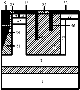
[0029] Such as figure 1 As shown, a split-gate trench power device with double vertical field plates, its cell structure includes a second doping type substrate 1, SiO 2 Buried oxide layer 21, first doping type drift region 31, dielectric trench region 22, second doping type strip 43, second doping type well region 42, first doping type source heavily doped region 32, second doping type Two doping type source heavily doped region 41, first doping type drain heavily doped region 33, shallow trench gate contact electrode 51, source contact electrode 52, drain contact electrode 53, gate floating field plate 54. Source field plate 55, drain field plate 56, gate oxide groove 23, gate-source covering dielectric layer 24, source-drain covering dielectric layer 25; the upper surface of the second doping type substrate 1 is provided with SiO 2 Buried oxide layer 21; the SiO 2The upper end surface of the buried oxide layer 21 is provided with a first doping type drift region 31; the f...

Embodiment 2

[0031] Such as figure 2 As shown, this embodiment is basically the same as Embodiment 1, except that the trapezoidal gate electrode 51 and the gate oxide groove 23 in the structure are trapezoidal gate structures.

Embodiment 3

[0033] Such as image 3 As shown, this embodiment is basically the same as Embodiment 1, the difference is that the material of the gate oxide groove 23 is changed to a low-K material 61, and the low-K material 61 reduces the dielectric constant between the gate and the drain to reduce the gate-drain charge, And an additional electric field spike is introduced to modulate the surface electric field.


PUM


Abstract

The invention belongs to the technical field of power semiconductors, in particular to a separated gate groove type power device with dual longitudinal field plates. A main characteristic of that invention is that a separation gate is introduce into the drift region, the thickness of the gate oxide layer between the gate electrode and the drain electrode is increase to reduce the gate drain chargeQGD, the volume electric field distribution is optimized, and the breakdown voltage of the device is increased; By introducing two longitudinal field plates into the dielectric groove, the contact area between the gate and drain is reduced, the gate-drain charge QGD is further reduced, and the on-resistance of the device is reduced by assisting the depletion drift region, and the internal electric field distribution of the device is further modulated to increase the breakdown voltage of the device. Longitudinal RESURF technique is used to introduce longitudinal P-pillar into the right side ofthe dielectric slot to further modulate the internal electric field of the device and increase the breakdown voltage of the device. Finally, the gate-drain charge is reduced, the device withstand voltage is improved, and the specific on-resistance is reduced.

Description

technical field [0001] The invention belongs to the technical field of power semiconductors, and relates to a split-gate-trough power device with double vertical field plates. Background technique [0002] There are two development directions for power semiconductor devices, one is to have a larger withstand voltage BV and a lower specific on-resistance R on,sp , but due to the existence of the inherent "silicon limit" of semiconductor devices, that is, the relationship between breakdown voltage and specific on-resistance is 2.5 power, which limits the development of power devices. The other is to develop towards low on-resistance and faster switching speed (that is, smaller gate-drain capacitance Cgd or gate charge Qgd), that is, smaller R on,sp ×Q GD,sp . [0003] In order to alleviate these two contradictions and make the device have lower specific on-resistance and gate-to-drain charge under the premise of meeting a certain breakdown voltage, the present invention int...

Claims


Application Information

Patent Timeline
IPC IPC(8): H01L29/78H01L29/423H01L29/40H01L29/06
CPCH01L29/063H01L29/407H01L29/42364H01L29/7824H01L29/7825
Inventor 吴丽娟黄也朱琳雷冰吴怡清张银艳
Owner CHANGSHA UNIVERSITY OF SCIENCE AND TECHNOLOGY
Why Eureka
Try Eureka