Eureka AIR delivers breakthrough ideas for toughest innovation challenges, trusted by R&D personnel around the world.

An electric-assisted heating forming device and method for pipe fittings with complex cross-sections made of dissimilar materials

A heat forming technology of dissimilar materials, applied in the direction of forming tools, metal processing equipment, manufacturing tools, etc., can solve the problems of easy cracking of welds, uncoordinated deformation, and thinning of pipe fittings, so as to promote the coordination of deformation and increase the effective Material, addressing the effects of fitting shape and size variations

Active Publication Date: 2020-02-21
NANJING UNIV OF AERONAUTICS & ASTRONAUTICS
View PDF12 Cites 0 Cited by
  • Summary
  • Abstract
  • Description
  • Claims
  • Application Information

AI Technical Summary

Problems solved by technology

[0009] In view of the above problems, the present invention proposes an electric-assisted heating inflatable forming device and forming method for complex cross-section pipe fittings of dissimilar materials. Problems such as severe deformation and thinning in the area of ​​large expansion rate, etc., realize rapid prototyping of pipe fittings with complex cross-sections of dissimilar materials

Method used


Image

  • An electric-assisted heating forming device and method for pipe fittings with complex cross-sections made of dissimilar materials
  • An electric-assisted heating forming device and method for pipe fittings with complex cross-sections made of dissimilar materials
  • An electric-assisted heating forming device and method for pipe fittings with complex cross-sections made of dissimilar materials

Examples


Embodiment 1

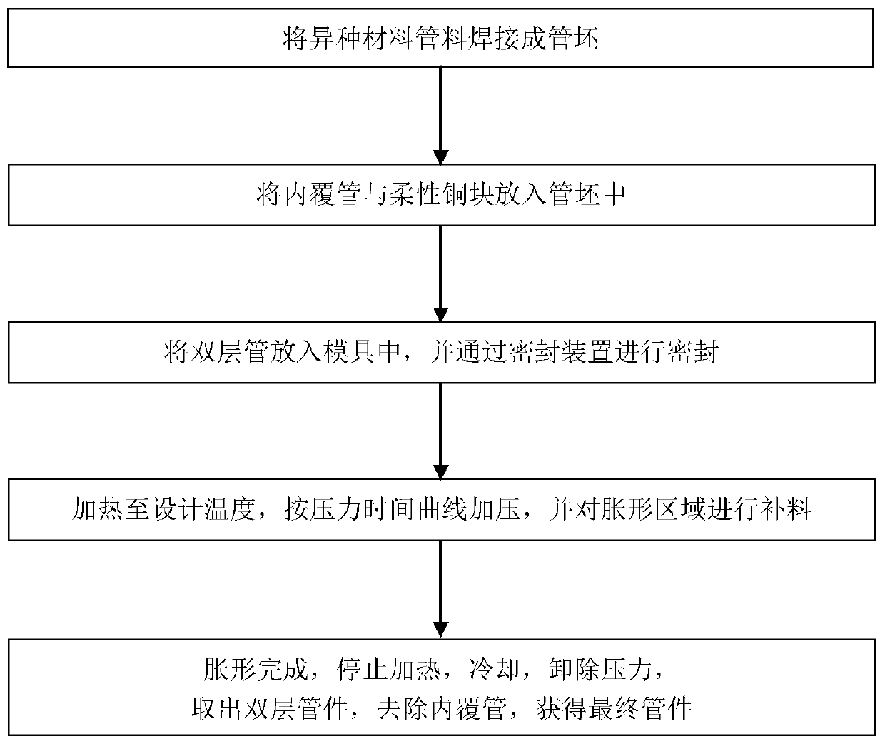
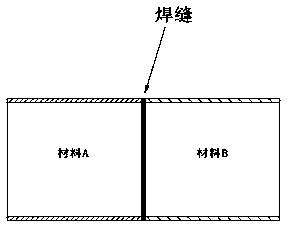
[0058] like figure 2 As shown, the tube blank 9 to be processed is welded by a pipe fitting whose material is A and a pipe whose material is B;

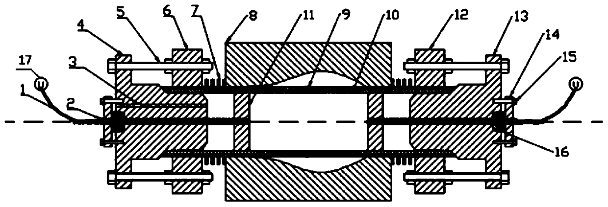
[0059] like image 3 The electric-assisted heating inflatable forming device for pipe fittings with complex cross-sections of dissimilar materials shown,

[0060] It includes: an inner covering pipe 10 with non-uniform distribution of wall thickness placed in the tube blank 9 and matched with its clearance, an inflatable forming mold 8 sleeved on the tube blank 9, and an inflatable forming mold 8 sleeved on the tube blank 9 and positioned on the inflatable forming mold 8 The constraining collars 7 on both sides, the left indenter 6 and the right indenter 12 which are respectively sleeved on the two ends of the tube blank 9 and welded to it, are connected with the left indenter 6 by a bolt 5 and one end extends into the inner covering The left seal push head 4 in the pipe 10, the right seal push head 13 that is connected with the r...

Embodiment 2

[0077] like figure 2 As shown, the tube blank 9 to be processed is welded by a pipe fitting of material A and a pipe fitting of material B;

[0078] Adjustable local area electric heating inflatable forming device for complex cross-section pipe fittings of dissimilar materials, such as Figure 7 As shown, the difference between it and the inflation forming device in Embodiment 1 is that the structure of the inner cavity of the inflation forming mold 8 is different, and the inner cavity of the inflation forming mold 8 in Embodiment 1 is a circumferential curved surface cavity, while the inner cavity of the inflatable molding die 8 in the second embodiment is two circumferentially curved concave cavities alternated with different cross-sections.

[0079] A method for forming a pipe fitting with a complex cross-section of dissimilar materials with adjustable local area electric heating and inflation, refer to figure 1 , 2 , 6, 7 and 8, steps one to five of the method are iden...


PUM


Abstract

The invention discloses an electric assistant heating forming device and method for dissimilar material complicated section pipe fittings. Pipe blanks welded by dissimilar material pipes and inner coating pipes positioned in the pipe blanks are positioned in an air expansion forming mold; two ends of the pipe blanks are sealed through sealing push heads and elastic sealing blocks; the positions offlexible copper blocks are adjusted by using advancement and retreating of push rods to realize local area heating; high-pressure gas is injected in the inner coating pipes to enable the pipe blanksto quickly bond on molds; meanwhile, the push heads are pushed for feeding; after formation, the heating is stopped; the high-pressure gas in the pipe blanks is relieved; formed double-layer pipe fittings are taken out; and the inner coating pipes are removed through acid washing to obtain final pipe fittings. The device and the method are suitable for expansion of the dissimilar material pipes, solve the problems of inharmonious deformation in expansion of traditional dissimilar material pipe blanks and rupture of welding lines through local heating and coating plate expansion, also can be used for gradual formation of pipe fittings in multiple expansion areas, meet urgent demands in such fields as aerospace, and achieve high practical value.

Description

technical field [0001] The invention relates to an electric-assisted heating forming device and method for pipe fittings with complex cross-sections made of different materials, and belongs to the field of processing metal plates or pipes, rods or profiles. Background technique [0002] In order to obtain ideal structural strength and adapt to specific use environments, tubular parts often have complex axes and constantly changing cross-sectional shapes and sizes along the axial direction. Combustion chamber, tail nozzle, etc.; at the same time, in order to meet the requirements of light weight, good service performance, safety and reliability, etc., the processing method of applying high pressure inside the tube blank to cause the tube blank to bulge is often used. [0003] In fact, for complex pipe fittings in high-temperature service such as tail nozzles and air inlets, the service temperature and requirements of each area are different during use. At the same time, the ...

Claims


Application Information

Patent Timeline
Patent Type & Authority Patents(China)
IPC IPC(8): B21D26/051B21D26/045B21D26/059B21D37/16
CPCB21D26/045B21D26/051B21D26/059B21D37/16
Inventor 武永吴迪鹏范荣磊陈明和谢兰生
Owner NANJING UNIV OF AERONAUTICS & ASTRONAUTICS
Why Eureka
Eureka Blog
Learn More