Electrostatic chuck device
An electrostatic chuck and electrode technology, which is applied in the direction of holding devices, circuits, and electrical components that apply electrostatic attraction, can solve problems such as temperature distribution on the wafer surface, and achieve the effect of improving uniformity
- Summary
- Abstract
- Description
- Claims
- Application Information
AI Technical Summary
Problems solved by technology
Method used
Image


Examples
no. 1 Embodiment approach ”
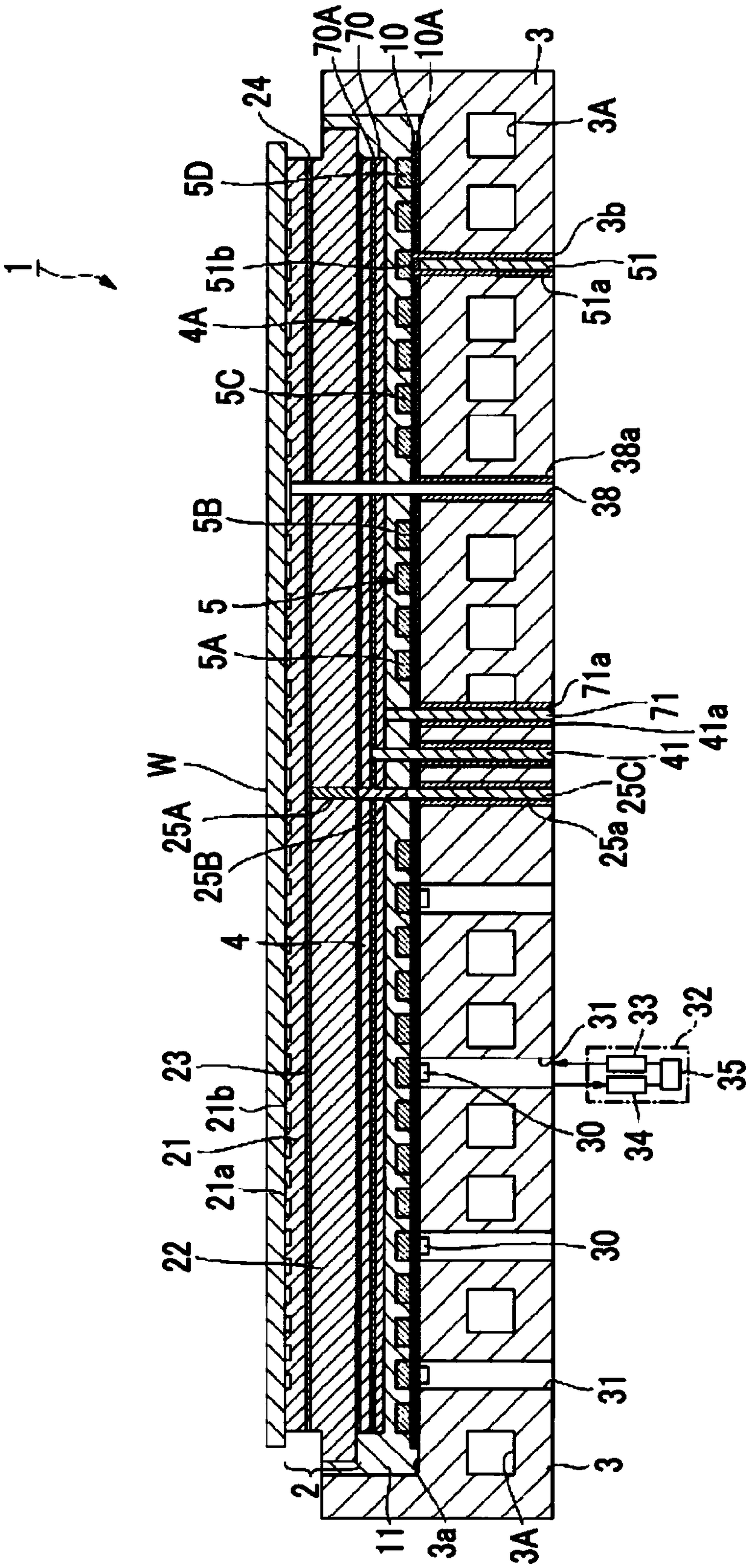
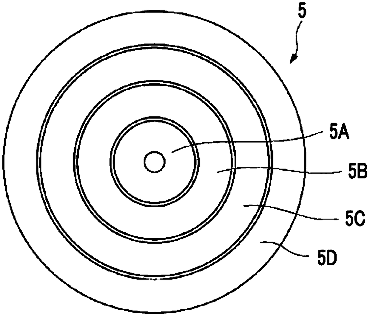
[0131] figure 1 It is a sectional view showing the electrostatic chuck device according to the first embodiment of the present invention. The electrostatic chuck device 1 of this form has: a disk-shaped electrostatic chuck part 2, one main surface (upper surface) side is used as a mounting surface; a disk-shaped temperature-adjusting base part 3 is provided on the electrostatic chuck. The bottom of the disk part 2, and has the thickness that adjusts the electrostatic chuck part 2 to a desired temperature; the electrode 4 for high-frequency generation is sandwiched between the electrostatic chuck part 2 and the base part 3 for temperature adjustment; A high-frequency power supply (not shown in the figure) is connected to the high-frequency generating electrode; the first heating element 5 is arranged between the high-frequency generating electrode 4 and the temperature adjustment base part 3 in layers, and includes a plurality of main heating elements. device; and the protecti...
no. 2 Embodiment approach ”
[0197] Figure 4 It is a sectional view showing the electrostatic chuck device according to the second embodiment of the present invention. The electrostatic chuck device 101 of this form is different in that a second heating element is provided between the first heating element 5 and the temperature adjustment base portion 3 . In addition, the insulating plates 7 and 8, the wiring layer 9 interposed between the insulating plates 7 and 8, and the adhesive for bonding the insulating plate 7 to the base part 3 for temperature adjustment are disposed along with the second heating element. Connect layer 7A.
[0198] exist Figure 5 Among them, the second heating element 6 is arranged in layers between the first heating element 5 and the base portion 3 for temperature adjustment. On the other hand, it may be arranged between the first heating element 5 and the protective electrode 70 . In either case, the guard electrode 70 blocks the high frequency generated by the high freque...
no. 3 Embodiment approach ”
[0226] Figure 7 It is a cross-sectional view showing an electrostatic chuck device according to a third embodiment of the present invention. The electrostatic chuck device 501 of this form is provided with: a disk-shaped electrostatic chuck part 502 with one main surface (upper surface) side as a mounting surface; a disk-shaped temperature-adjusting base part 503 provided on the electrostatic chuck The bottom of the disk part 502, and has a thickness to adjust the electrostatic chuck part 502 to a desired temperature; the layered structure of the high-frequency generation electrode 550 is sandwiched between the electrostatic chuck part 502 and the temperature adjustment base part 503 Between; the first heating element 505 of layered structure is sandwiched between the electrostatic chuck part 502 and the electrode 550 for generating high frequency; the second heating element 506 of layered structure is sandwiched between the electrode 550 for generating high frequency betwee...
PUM
 Abstract
Description
Claims
Application Information
 - R&D
- Intellectual Property
- Life Sciences
- Materials
- Tech Scout
- Unparalleled Data Quality
- Higher Quality Content
- 60% Fewer Hallucinations
Browse by: Latest US Patents, China's latest patents, Technical Efficacy Thesaurus, Application Domain, Technology Topic, Popular Technical Reports.
© 2025 PatSnap. All rights reserved.Legal|Privacy policy|Modern Slavery Act Transparency Statement|Sitemap|About US| Contact US: help@patsnap.com