
Heat exchanger

A technology of heat exchangers and heat exchange tubes, which is applied to fluid heaters, lighting and heating equipment, etc., and can solve problems such as long length of water pipes, high cost of heat exchangers, and affecting users' bathing comfort

Pending Publication Date: 2019-01-01
GUANGDONG VANWARD NEW ELECTRIC CO LTD
View PDF0 Cites 3 Cited by
  • Summary
  • Abstract
  • Description
  • Claims
  • Application Information

AI Technical Summary

Problems solved by technology

[0002] In the prior art, most of the heat exchangers used in the general gas water heater industry are made of oxygen-free copper. The surface of the combustion chamber is covered with coils. The length of the water pipe is long, the heating is slow, and the water resistance in the pipe is large. The flow rate is small, which affects the user's comfortable bathing style, and a large amount of copper is used, resulting in high overall cost of the heat exchanger; and the current stainless steel heat exchanger, due to problems such as heat exchange tube shape and heat exchange fin design, causes heat exchangers The heat transfer effect is not ideal, and the heat transfer efficiency is not high

Method used


Image

  • Heat exchanger
  • Heat exchanger
  • Heat exchanger

Examples


Embodiment Construction

[0025] The specific implementation manners of the present invention will be further described in detail below in conjunction with the accompanying drawings and embodiments. The following examples are used to illustrate the present invention, but are not intended to limit the scope of the present invention.

[0026] In the description of the present invention, it should be understood that the orientation or positional relationship indicated by the terms "upper", "lower", "left", "right", "top", "bottom" etc. Orientation or positional relationship is only for the convenience of describing the present invention and simplifying the description, and does not indicate or imply that the referred device or element must have a specific orientation, be constructed and operated in a specific orientation, and thus should not be construed as a limitation of the present invention. It should be understood that the terms "first", "second", etc. are used in the present invention to describe va...


PUM


Abstract

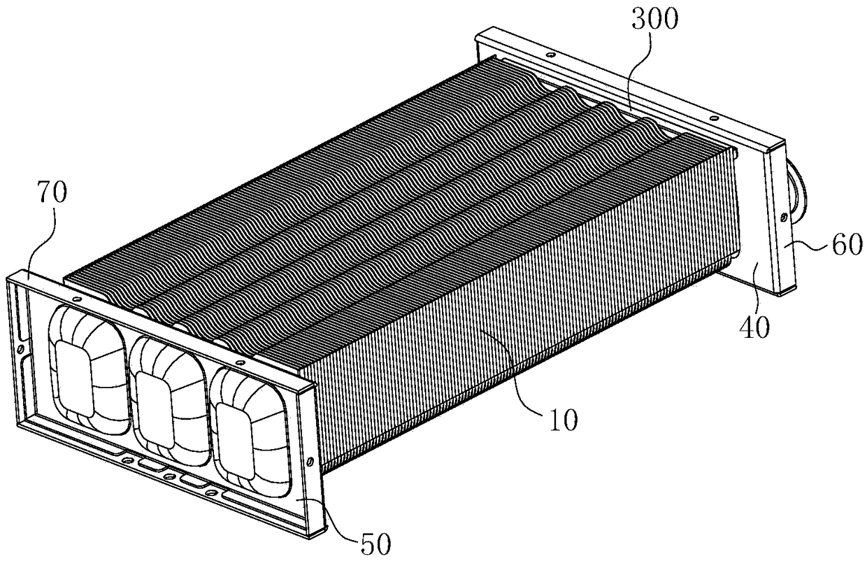
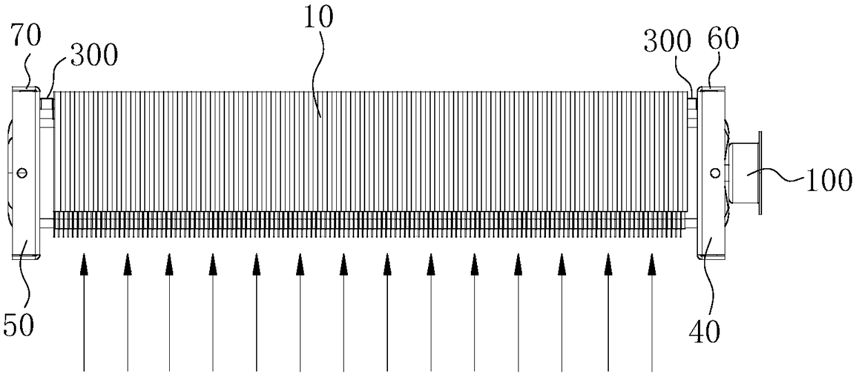
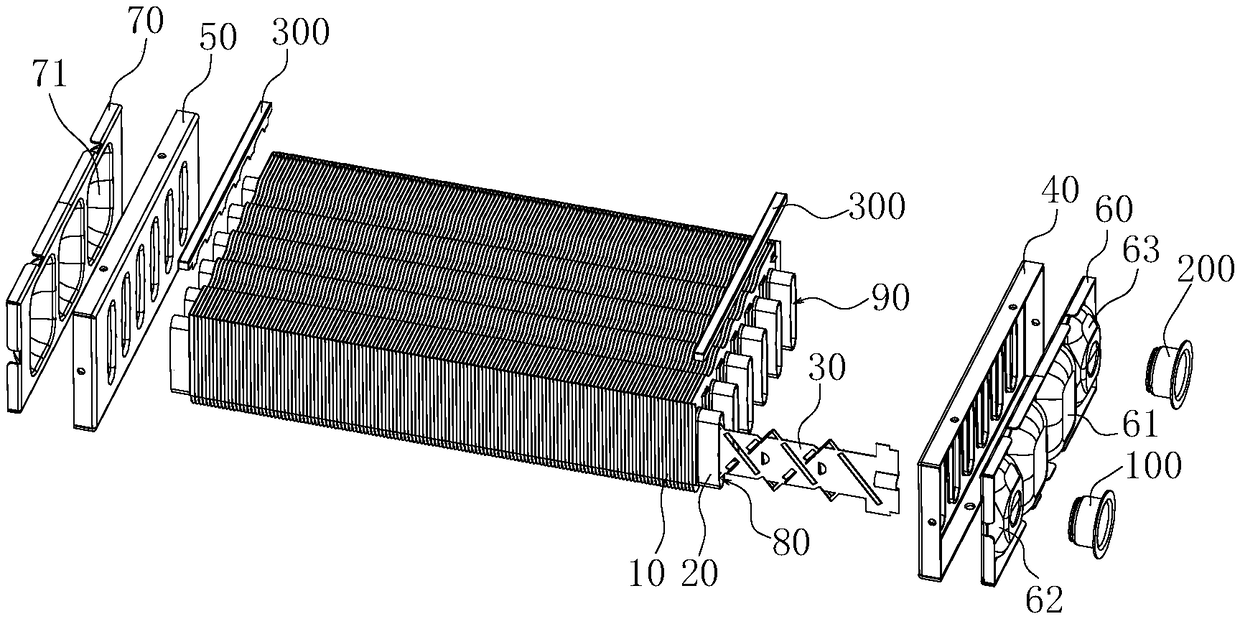
The invention discloses a heat exchanger. The heat exchanger comprises a fin assembly and a plurality of heat exchange tubes, wherein the fin assembly comprises a plurality of heat exchange pieces which are stacked at intervals, and a heat exchange channel for flue gas circulation is defined between every two adjacent heat exchange pieces; the heat exchange tubes are arranged in the fin assembly in an inserted manner through the heat exchange pieces, and the heat exchange tubes sequentially communicate with one another to form a water flow channel; and each heat exchange tube is a waist-shapedflat tube, and the length direction of the cross section of each heat exchange tube is parallel to the inflow direction of flue gas. The heat exchange tube has the beneficial effects that the heat exchange tubes are arranged to be the flat tubes, the length direction of the cross section of each heat exchange tube is parallel to the inflow direction of the flue gas, and therefore the effective heat exchange area can be increased; and the heat efficiency is guaranteed, the water path system can be properly shortened and simplified, and the cost of the heat exchanger is reduced.

Description

technical field [0001] The invention relates to the technical field of heat exchange equipment, in particular to a heat exchanger for a gas water heater. Background technique [0002] In the prior art, most of the heat exchangers used in the general gas water heater industry are made of oxygen-free copper. The surface of the combustion chamber is covered with coiled pipes. The length of the water pipe is long, the heating is slow, and the water resistance in the pipe is large. The flow rate is small, which affects the user's comfortable bathing style, and a large amount of copper is used, resulting in high overall cost of the heat exchanger; and the current stainless steel heat exchanger, due to problems such as heat exchange tube shape and heat exchange fin design, causes heat exchangers The heat exchange effect is not ideal, and the heat exchange efficiency is not high. Contents of the invention [0003] The purpose of the present invention is to overcome the deficienci...

Claims


Application Information

Patent Timeline
Patent Type & Authority Applications(China)
IPC IPC(8): F24H9/18
CPCF24H9/1836
Inventor 卢楚鹏唐元锋
Owner GUANGDONG VANWARD NEW ELECTRIC CO LTD
Learn More