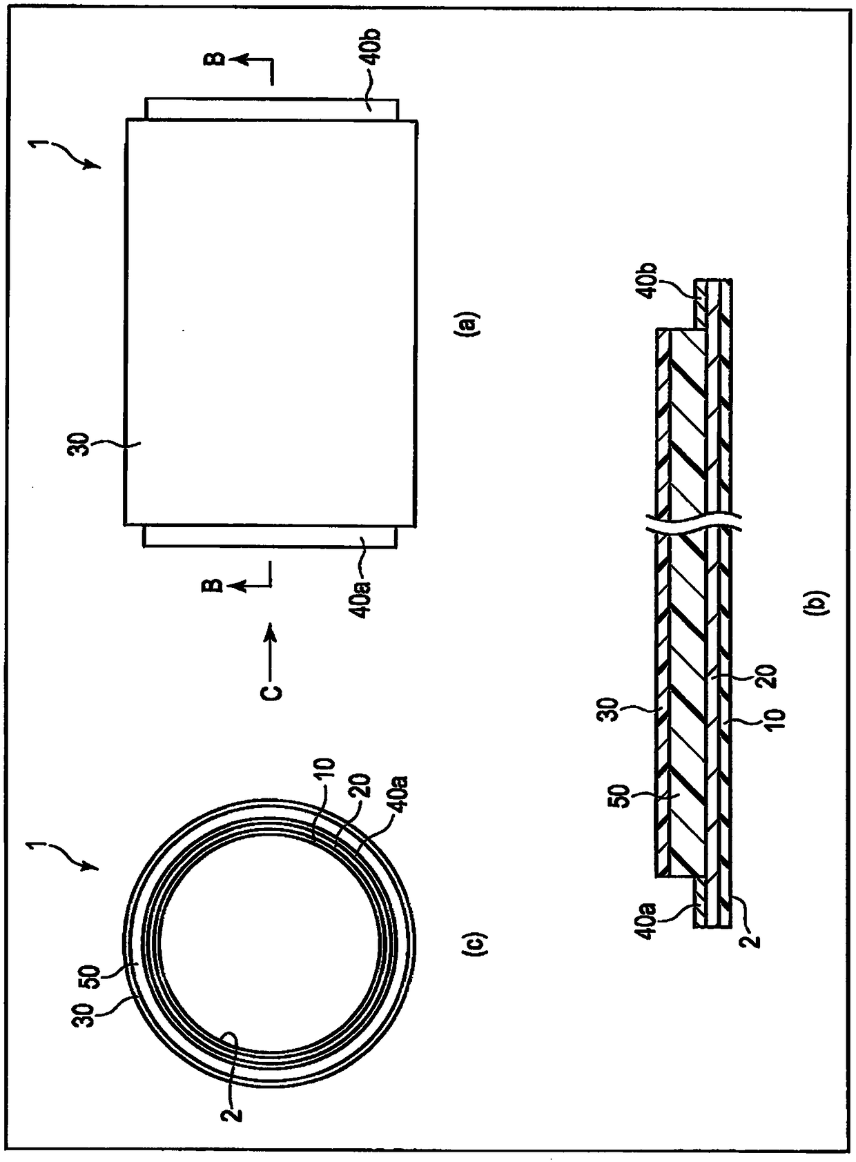
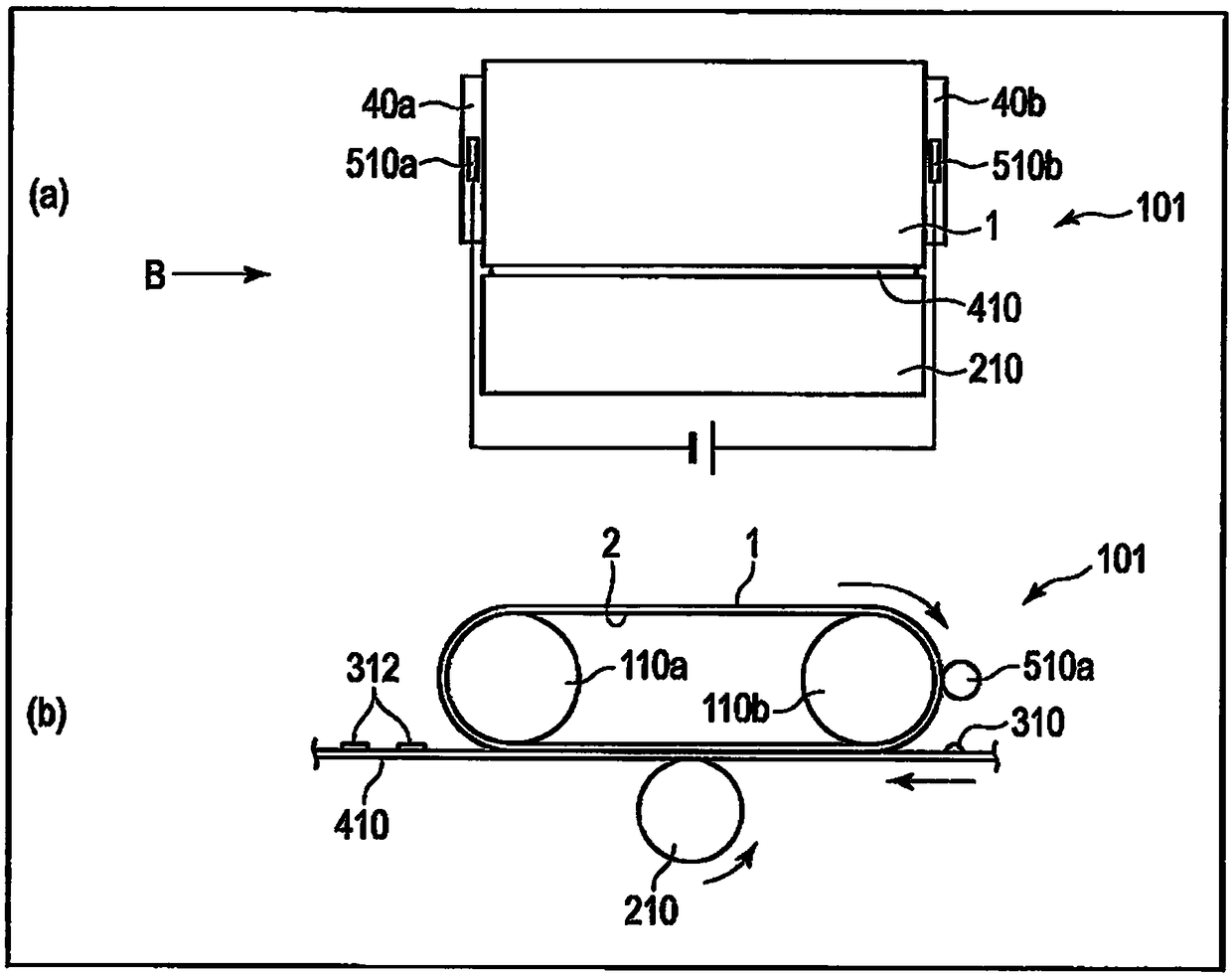
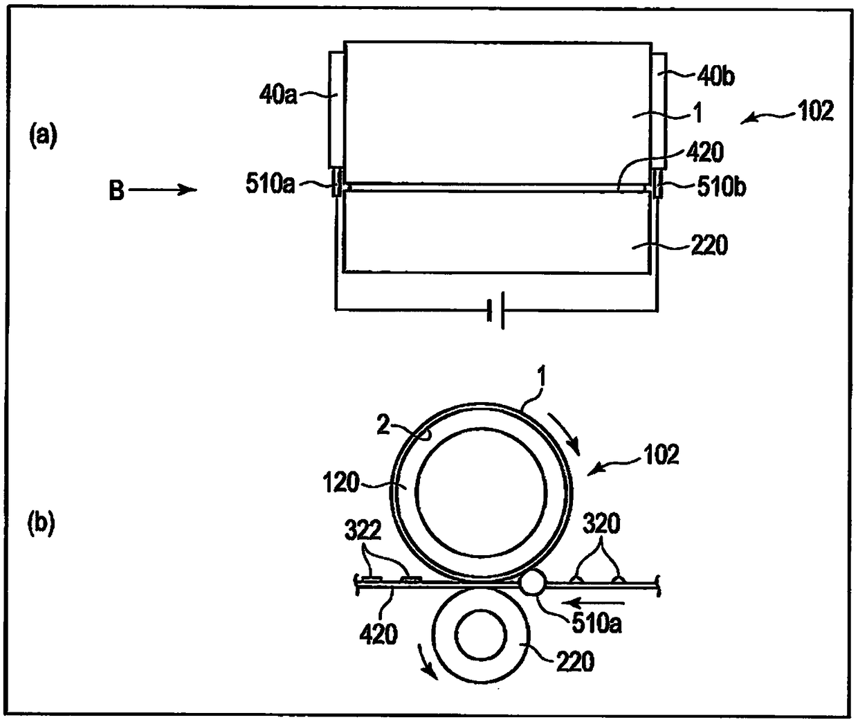
Heat fixing belt, method for producing heat fixing belt, and image fixation device
A fixing belt and heat-generating layer technology, which is applied in the direction of electrical recording technology using charge graphics, equipment and instruments using electrical recording technology using charge graphics, can solve problems such as unrealized adhesion, and achieve excellent bending resistance and Durability, reduction of volume resistance value, excellent effect of bending resistance and durability
- Summary
- Abstract
- Description
- Claims
- Application Information
AI Technical Summary
Problems solved by technology
Method used
Image
Examples
Embodiment 1
[0094] (1) Forming of the substrate layer
[0095] A stainless steel tube with an outer diameter of 30 mm and a total length of 350 mm was coated with polyamic acid (U-varnish-S, manufactured by Ube Industries, Ltd.) with a film thickness of 400 μm. Thereafter, it was dried at 120° C. for 60 minutes, heated up to 200° C. over 30 minutes, and kept at 200° C. for 30 minutes. Next, the temperature was raised to 380° C. over 30 minutes and kept at 380° C. for 15 minutes to complete the imidization reaction. Thereafter, after cooling to room temperature, the stainless steel tube was pulled out, and the end was cut off to obtain a seamless tubular body of polyimide resin with an inner diameter of 30 mm, a thickness of 70 μm, and a length of 240 mm.
[0096] A stainless steel tube having an outer diameter of 30 mm and a length of 240 mm was inserted into the polyimide resin tubular body obtained above.
[0097](2) Preparation of elastic resistance heating layer material
[0098] A...
Embodiment 2
[0118] Except in the material of the elastic resistance heating layer, adjust the mixing amount of the dispersion of Ketjen Black so that the volume resistance value of the elastic resistance heating layer is 1×10 3 Except for Ω·cm, a heat-generating fixing belt was produced in the same manner as in Example 1. The mixing amount of Ketjen Black was 10% by weight relative to 100% by weight of fluororubber in the solid content at this time, and the thickness of the elastic resistance heating layer was 220 μm.
Embodiment 3
[0120] In addition to the material of the elastic resistance heating layer, the mixing amount of the carbon nanotube dispersion (CNTD series, developed product; manufactured by Mikuni Pigment Co., Ltd.) is adjusted so that the volume resistance value of the elastic resistance heating layer is 1×10 -3 Except for Ω·cm, a heat-generating fixing belt was produced in the same manner as in Example 1. The mixing amount of carbon nanotubes was 50% by weight relative to 100% by weight of fluororubber in the solid content at this time, and the thickness of the resistance heating layer was 38 μm.
PUM
 Abstract
Description
Claims
Application Information
 - R&D Engineer
- R&D Manager
- IP Professional
- Industry Leading Data Capabilities
- Powerful AI technology
- Patent DNA Extraction
Browse by: Latest US Patents, China's latest patents, Technical Efficacy Thesaurus, Application Domain, Technology Topic, Popular Technical Reports.
© 2024 PatSnap. All rights reserved.Legal|Privacy policy|Modern Slavery Act Transparency Statement|Sitemap|About US| Contact US: help@patsnap.com


