
Method for manufacturing additives by combining selective laser melting and laser cutting

A laser selective melting and laser cutting technology, applied in the field of additive manufacturing, can solve the problems of short molten pool existence time, large temperature gradient, and increased voids in parts, and achieve the effect of improving smoothness, eliminating cracks and high performance

Inactive Publication Date: 2018-12-21
JIANGSU UNIV
View PDF4 Cites 18 Cited by
  • Summary
  • Abstract
  • Description
  • Claims
  • Application Information

AI Technical Summary

Problems solved by technology

[0003] However, similar to other additive manufacturing processes, since selective laser melting is a rapid prototyping process, the surface tension of the molten metal is very high, so it is easy to produce a spheroidization effect, resulting in an increase in internal voids and a decrease in density and strength; metal powder melting Fast, the molten pool exists for a short time, and there is a large temperature gradient during rapid solidification and forming, so that it is easy to generate large thermal stress. The thermal expansion coefficients of different tissues are different, which will generate tissue stress, and there are residual stresses in the solidified tissue. The combined action of the three stresses will lead to cracks in the workpiece
In addition, the surface roughness of the parts manufactured by the laser selective melting process is poor, and subsequent machining or polishing is required to improve the surface finish and precision of the parts
These subsequent processing steps not only reduce the manufacturing efficiency of the parts, but more importantly, it is impossible to process some parts (such as inner holes, etc.) that the tool cannot enter, and cannot improve its surface quality.
Therefore, the poor surface finish of parts has become a bottleneck problem of additive manufacturing technology

Method used


Image

  • Method for manufacturing additives by combining selective laser melting and laser cutting
  • Method for manufacturing additives by combining selective laser melting and laser cutting
  • Method for manufacturing additives by combining selective laser melting and laser cutting

Examples


Embodiment

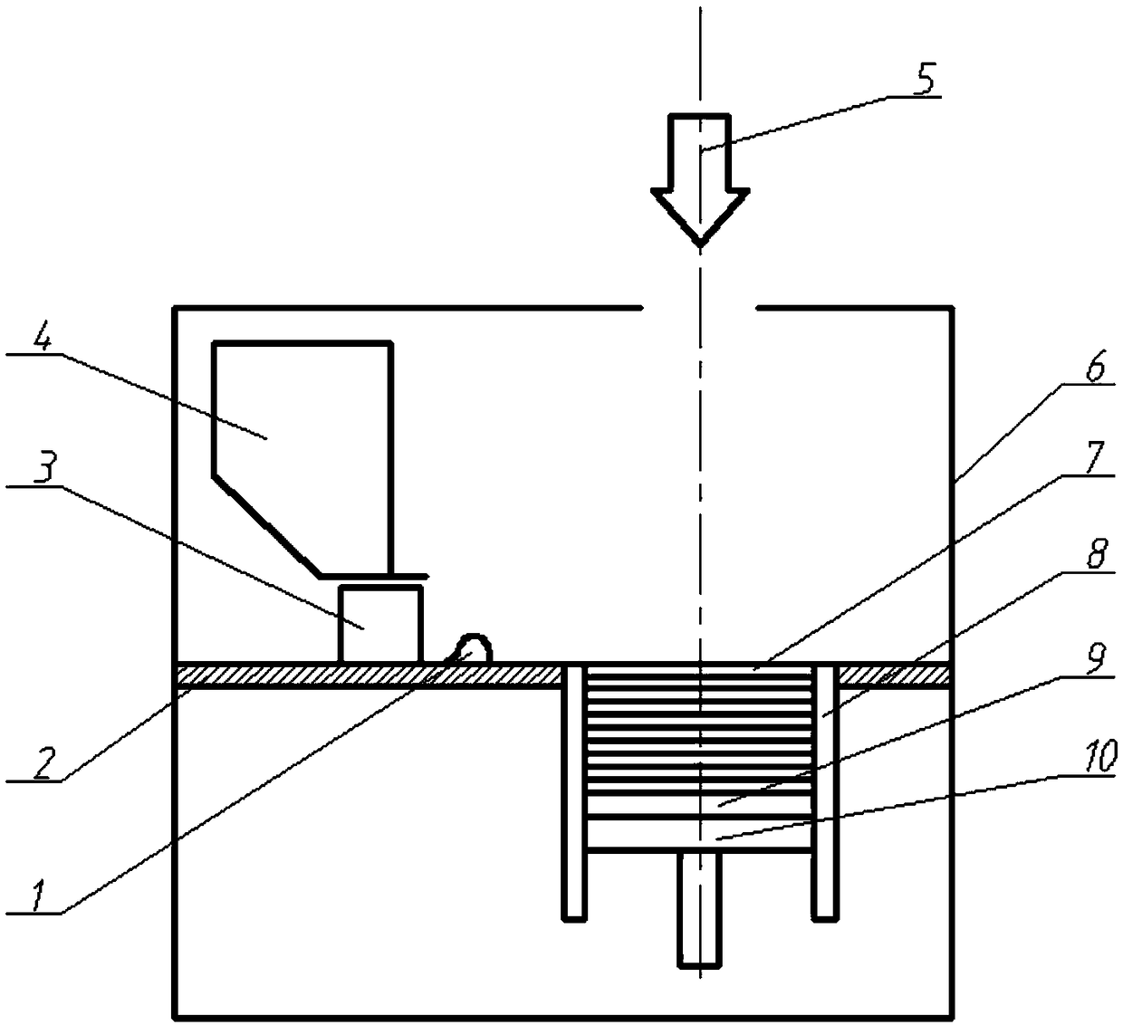
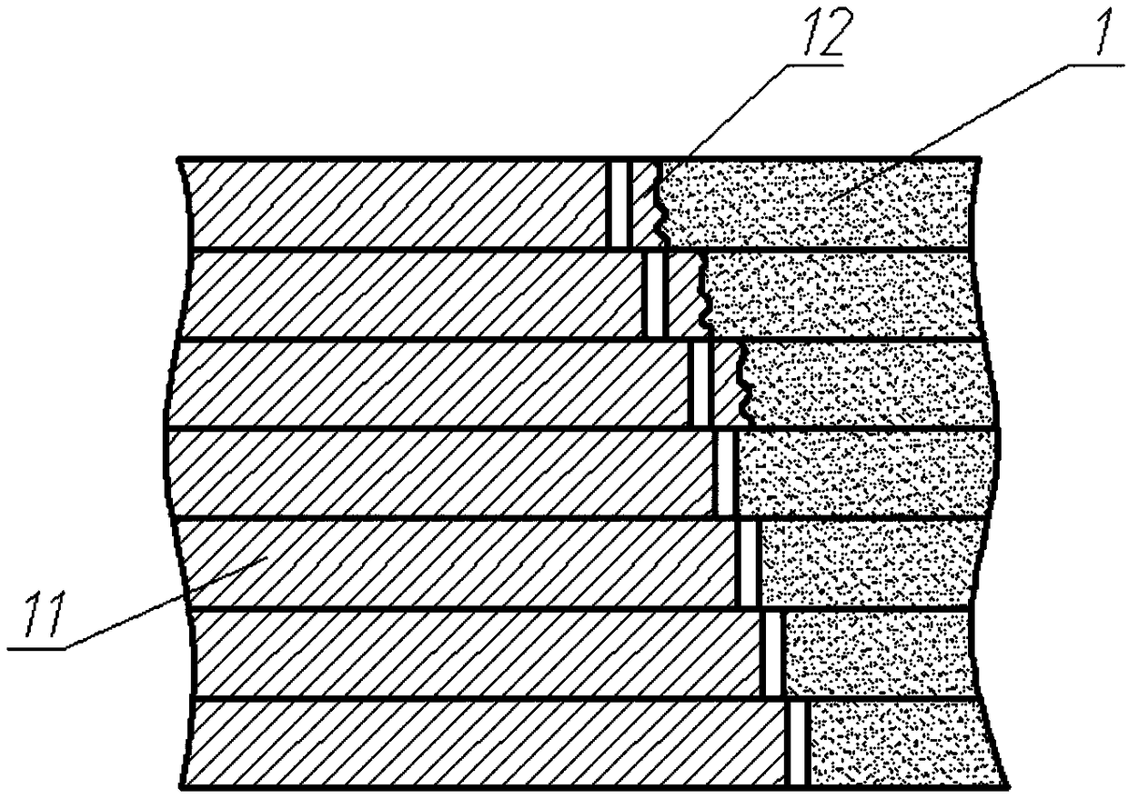
[0025] refer to figure 1 and figure 2 , the present embodiment relates to a combined additive manufacturing method of laser selective melting and laser cutting, comprising the following steps:

[0026] 1) Clean the surface of the TC4 substrate with an alkaline solution to remove oil stains, then polish and remove the oxide film on the surface of the substrate 9 and wipe it dry with acetone; A height difference of powder layer thickness is formed on the surface of the surface; under the control of the control computer, the powder feeder 4 outputs a certain amount of TC4 powder 1 and falls on the surface of the working platform 2, and then the powder laying device 3 pushes the TC4 powder 1 to the forming In the cylinder 8 and flat on the forming area of ​​the substrate 9 .

[0027] 2) First emit the laser beam 5 in the heating mode to scan and preheat the TC4 powder bed 7 to heat the TC4 powder to the micro-sintering temperature of 581°C to produce micro-sintering, wherein th...


PUM


Abstract

The invention relates to the technical field of additive manufacturing, in particular to a method for manufacturing additives by combining selective laser melting and laser cutting. The method for manufacturing additives by combining selective laser melting and laser cutting comprises the following steps that (1) the surface of a substrate is cleaned with an alkaline solution to remove oil stains,then an oxide film on the surface of the substrate is polished and removed, and the surface of the substrate is wiped with acetone; (2) firstly, a laser beam in a heating mode is emitted to scan andpreheat a powder bed, so that a powder material is heated to a micro-sintering temperature to generate micro-sintering; (3) then a laser beam in a selective melting mode is emitted to scan and melt the preheated powder bed to form a required workpiece cross-sectional layer; (4) finally a laser beam in a laser cutting mode is emitted to perform one or more times of cutting scan on the inner and outer contours of the workpiece cross-section to remove or cut rough edges and welding powder on the contours so as to obtain accurate and smooth inner and outer contours of the part cross-section; and (5) the heating, selective melting and cutting processes are repeated to finally obtain a required three-dimensional solid workpiece.

Description

technical field [0001] The invention relates to the technical field of additive manufacturing, in particular to an additive manufacturing method combining laser selective melting and laser cutting. Background technique [0002] High-precision flexible manufacturing is the goal pursued by the manufacturing industry. Therefore, the research and industrial development of additive manufacturing (or 3D printing) technology has become a hot spot today. Selective laser melting (SLM) technology is the latest rapid prototyping technology that has emerged in recent years. It uses layered manufacturing for additive manufacturing, and converts CAD models into physical parts through powder. It adopts laser rapid melting of selected metal powder and rapid cooling and solidification technology, which can obtain non-equilibrium supersaturated solid solution and uniform and fine metallographic structure, and has a wide range of forming materials. The manufacturing process is not limited by t...

Claims


Application Information

Patent Timeline
IPC IPC(8): B22F3/105B22F3/24B33Y10/00
CPCB22F3/24B33Y10/00B22F2003/247B22F10/00B22F10/28B22F10/366B22F12/43Y02P10/25
Inventor 鲁金忠卢海飞罗开玉
Owner JIANGSU UNIV
Learn More