A method and system for suppressing planar resonance by placing capacitor position

A resonant, planar technology, applied in the field of signal transmission, can solve problems such as planar resonance, achieve the effects of improving resonance, ensuring safety, and reducing ground bounce effects

Active Publication Date: 2018-12-18
SUZHOU LANGCHAO INTELLIGENT TECH CO LTD
View PDF4 Cites 1 Cited by
  • Summary
  • Abstract
  • Description
  • Claims
  • Application Information

AI Technical Summary

Problems solved by technology

[0005] The purpose of the present invention is to provide a method and system for suppressing plane resonance by arranging capacitor positions, aiming to solve the problem in the prior art that the cavity between the power supply layer and the ground layer will cause plane resonance, and to reduce The ground bounce effect reduces electromagnetic interference

Method used


Image

  • A method and system for suppressing planar resonance by placing capacitor position
  • A method and system for suppressing planar resonance by placing capacitor position
  • A method and system for suppressing planar resonance by placing capacitor position

Examples


Embodiment Construction

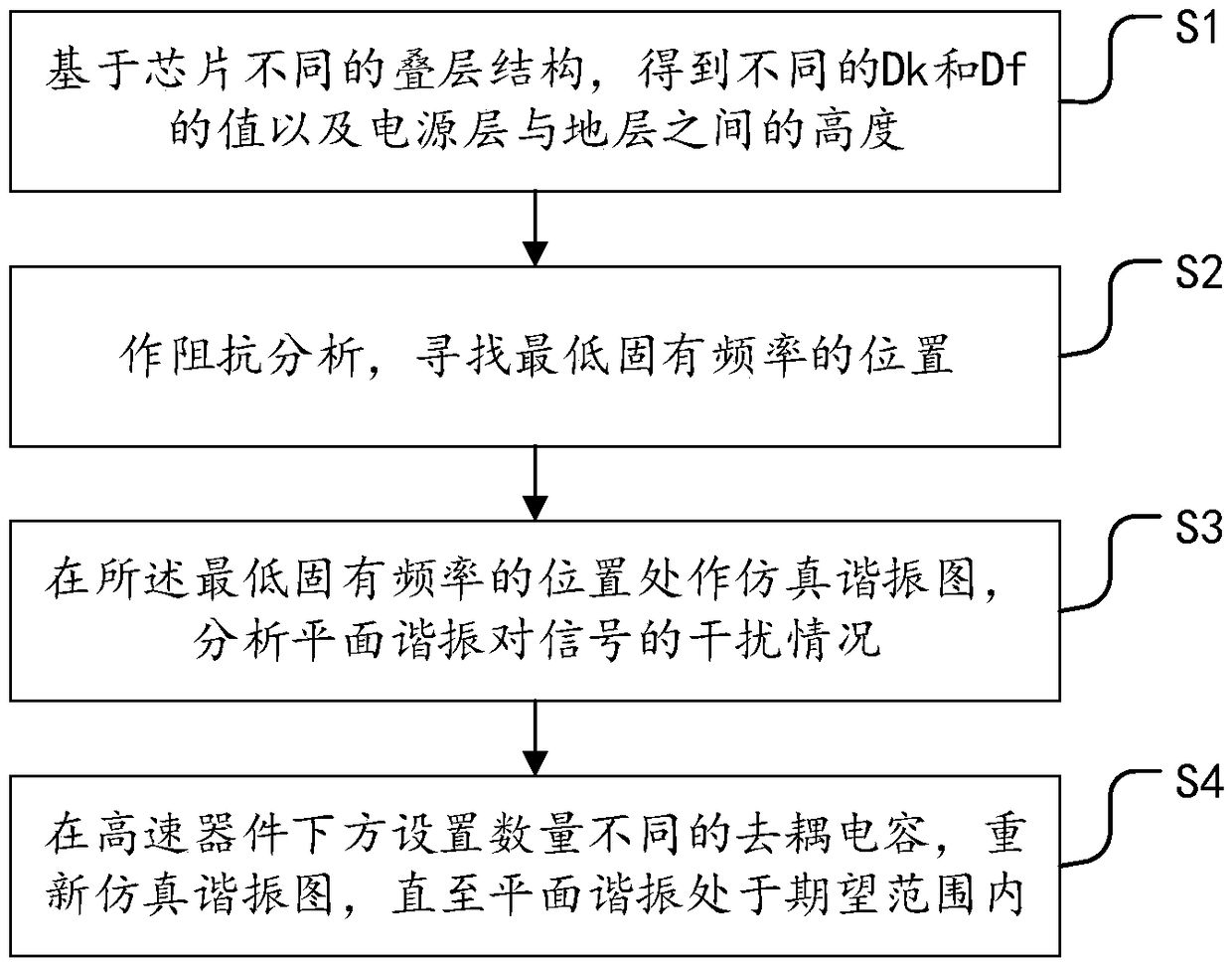
[0032] In order to clearly illustrate the technical features of the present solution, the present invention will be described in detail below through specific implementation methods and in conjunction with the accompanying drawings. The following disclosure provides many different embodiments or examples for implementing different structures of the present invention. To simplify the disclosure of the present invention, components and arrangements of specific examples are described below. Furthermore, the present invention may repeat reference numerals and / or letters in different instances. This repetition is for the purpose of simplicity and clarity and does not in itself indicate a relationship between the various embodiments and / or arrangements discussed. It should be noted that components illustrated in the figures are not necessarily drawn to scale. Descriptions of well-known components and processing techniques and processes are omitted herein to avoid unnecessarily lim...


PUM


Abstract

The invention provides a method and a system for suppressing plane resonance by placing a capacitor position, comprising the following steps: S1, obtaining different values of Dk and Df and a height between a power supply layer and a ground layer based on different stack structures of chips; S2, impedance analysis is performed to find the position of the lowest natural frequency; S3, simulating the resonance diagram at the position of the lowest natural frequency, and analyzing the interference of the plane resonance to the signal; S4, set a different number of decoupling capacitors beneath the high speed device and re-simulate the resonance pattern until the planar resonance is within the desired range. The purpose of improving the resonance of the frequency band is realized by changing the cavity formed between the power supply layer and the ground layer. The ground elastic effect caused by cavity resonance can be reduced, and the electromagnetic interference caused by the ground elastic effect can be reduced. The effect of de-resonance on signals caused by the fact the decoupling capacitor is placed in different positions is expressed.

Description

technical field [0001] The invention relates to the technical field of signal transmission, in particular to a method and system for suppressing plane resonance by arranging capacitor positions. Background technique [0002] In a multi-layer circuit board, it is usually divided into a power layer and a ground layer. A resonant cavity is formed between the large planes of the power supply and the ground layer. When high-speed digital signals pass through, the voltage between the power supply and ground fluctuates. Since it is resonance, it needs a natural frequency. This natural frequency is related to the shape of the power supply and ground plane, and the intermediate dielectric parameters (dielectric constant, loss, thickness). Once these parameters are fixed, the natural frequency is fixed. High-speed signals contain rich spectral components, some of which are the same as the natural frequency of the PCB power ground, so they fluctuate. If the lowest natural frequency i...

Claims


Application Information

Patent Timeline
Patent Type & Authority Applications(China)
IPC IPC(8): H05K1/02
CPCH05K1/0231
Inventor 刘法志
Owner SUZHOU LANGCHAO INTELLIGENT TECH CO LTD
Why Eureka
Try Eureka